
Note: Replace bolts that are overtightened. Aluminum bolts for attaching the engine to the manual transmission can be used 2 times. Replace self-locking nuts and bolts and seals. rings, gaskets and seals. cuffs Hose fittings, as well as air ducts and hoses of the air charging system must be cleaned of oil and grease before installation. Secure all hose connections with hose clamps of the appropriate standard. In order to securely fasten the hoses of the air charging system in their fittings, before installation, the screw spirals in the already used hose clamps should be sprayed with a corrosion solvent. When installing, install all cable ties in their original places.
Tightening torques when installing the gearbox
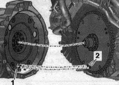
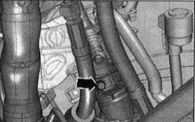
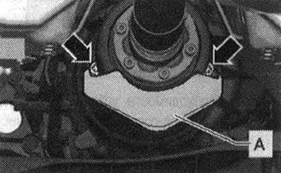
Place the gearbox on the gearbox mount -T40173- and secure with the tensioning belt -1- as shown in the illustration. Check the input shaft where it is installed in the driven disc -arrow- for signs of running-in. If necessary, replace the needle bearing of the driven disk.
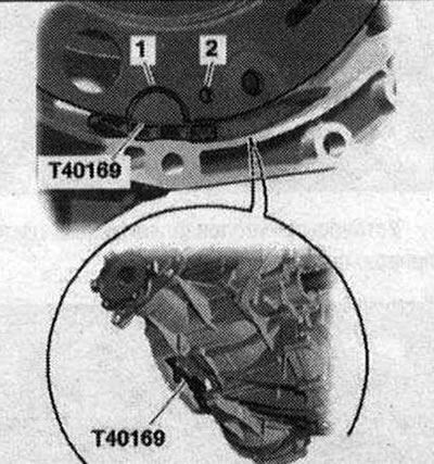
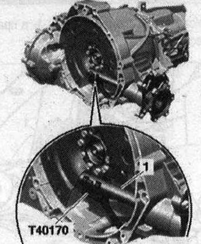
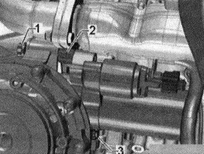
If necessary, install the clutch module. Before connecting the engine and gearbox, carry out the following preparatory steps. Install the mounting aid -T40169- from below into the gearbox housing and into the clutch module as shown in the illustration. The mounting device -T40169- must fit into the semicircular groove -1- and additionally into the inspection hole -2-. There is only one inspection hole around the perimeter; turn the clutch module accordingly. Insert the bolts of the mounting device into the hole on the gearbox housing. Install the transport protection -T40170- from below under the gearbox housing and attach it to the flange shaft -1-.
Place the transport protection -T40170- from below under the gearbox housing and attach it to the flange shaft -1-.
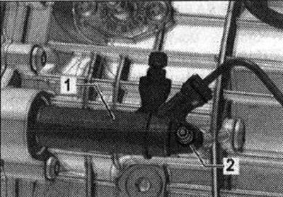
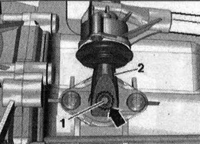
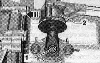
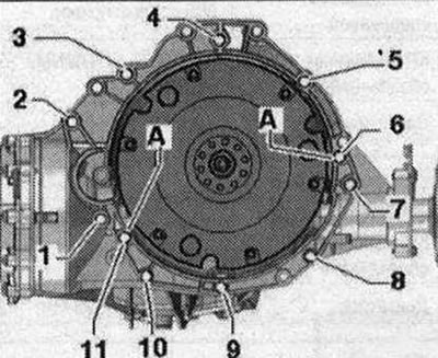
Check the presence of centering sleeves -A- for the engine and gearbox in the cylinder block, insert the sleeves if necessary. Raise the gearbox so that the clutch slave cylinder -1- can be installed. Tighten bolt -2-.
The next work step is only necessary if a driven disk with a locking pin -2- is installed. Additionally, align the position of the driven disk with respect to the clutch module so that the locking pins -2- (in the presence of) on the driven disc could fit into the large holes -1- on the clutch module. Problem in clutch operation if installed incorrectly If the locking pins of the driven disc -2- do not fit into the holes of the clutch module, this can lead to serious problems in the operation of the clutch.
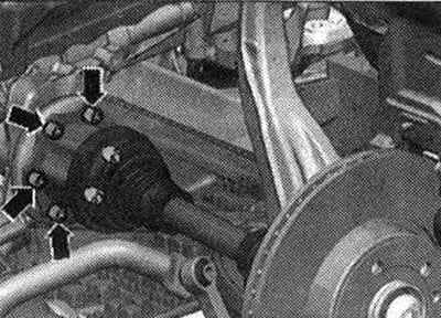
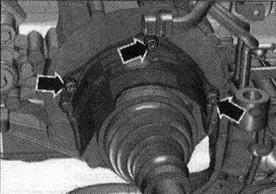
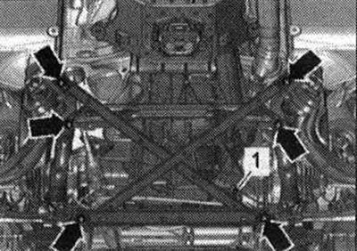
If necessary, check the possibility of reuse and mark the aluminum bolts -2...11- connecting the engine and gearbox. Place the engine on the gearbox and tighten the bolts -7...11- of the engine/gearbox connection. Bolt -7- is only installed on 4-cylinder TDI engines. Tighten the bolts -arrows- of the tunnel cross member.
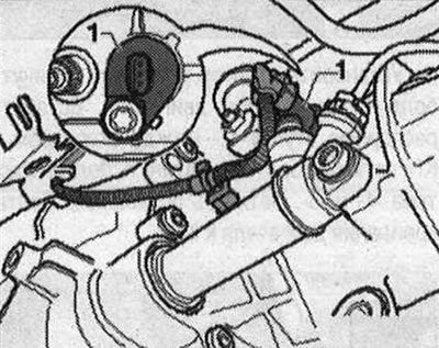
Vehicles with start-stop system: Connect connector for gearbox neutral position sensor -G701- -1-.
All
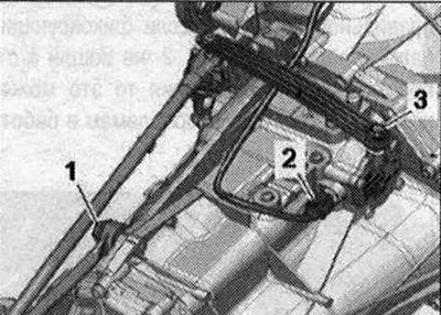
Install gearbox lever -2- as follows. Gear shift lever -2 - can be installed on the shift shaft -1 - only in one position (recess in ring gear -arrow-). Tighten the gearbox lever -2-.
Tighten the shift fork rod -1-.
Tighten connecting rod -3-. Connect email Plug connection -2 for gear detection sensor -F208-.
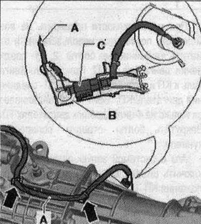
Pin (in the presence of) on the gearbox, bracket -B- with plug connector -C- for exhaust temperature sensor 4 -G648-. Secure email wire -A- to gearbox -arrows-.
Install the starter and hand-tighten the bolt -3- on the engine side. Insert spacer -2- between starter and gearbox, tighten bolt -1-. Tighten starter bolts -1- and -3-. Tighten the remaining bolts securing the engine to the gearbox.
Screw the universal joint to the steering gear.
Tighten the drive shaft bolts on the shafts with the gearbox flange.
Install the heat insulating shield of the drive shaft.
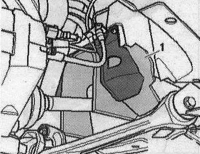
Install sound insulation -1- in the right wheel arch.
Install the driveshaft or screw it to the gearbox. Secure the cardan shaft. To do this, install the counter support-T10172-s -T10172/5- bolts securing the propeller shaft to the gearbox or rear final drive.
Torque sequence - clutch module to driven plate
Remove mounting device -T40169- and transport protection -T40170-. Engage 6th gear, to do this, remove the shift shaft -1- and shift the gearbox lever -2- forward in the -direction of the arrow-.
The next stage of work is necessary to ensure uniform contact with the driven disk without distortion. Rotate both front wheels in the same direction until the clutch module makes 1 full revolution. The inspection hole -arrow- should again be visible in the recess of the gearbox housing.
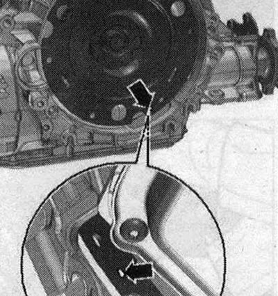
Tighten the clutch module bolts on the driven disc as follows. Use new bolts. Tighten the bolts using a 16 mm ring spanner -VAG 1332/14-. Screw in the first bolt -arrow- by hand (2 Nm).
Rotate the clutch module using the front wheels 120°in the direction of engine rotation and screw in the second bolt also by hand (2 Nm). Rotate the clutch module again 120°in the direction of engine rotation. Then screw in and tighten the third bolt. Now tighten the 2 remaining bolts. Install in reverse order. If fitted, install heat shield for propeller shaft -A- and tighten bolts -arrows- to 25 Nm.
Vehicles with 2.0l TDI engine: Install particulate filter and exhaust pipe. Install the air housing. filter.
All
Install the power steering lines.
Install the subframe spacer. Check the transmission oil level in the manual gearbox. Install sound insulation. Install a stretcher. Consider the measures required after connecting the battery. Risk of damage to control units due to overvoltage. Do not use a charger as a starting aid!
Tightening torques (Nm)
| Bolts and nuts | |
| M6 | 9 |
| M7 | 15 |
| M8 | 20 |
| M10 | 40 |
| M12 | 65 |
Thermal shield of the joint shaft - tightening torque
Tighten the bolts -arrows- of the heat insulation shield of the drive shaft to a torque of 23 Nm.
Mounting the 2.0-litre TDI engine to the manual gearbox
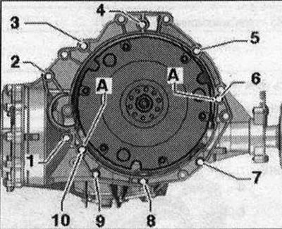
| Pos. | Bolt | Nm |
| 1 (1) | M 10x50 (2) | 65 |
| 2 (3) | M12x100 4) | 30 + 90° |
| 3 (5), 6 | M 12x75 (4) | 30 + 90° |
| 4, 5 (5) | M12x120 (4) | 30 + 90° |
| 7...9 | M1 0x75 (4) | 15 + 90° |
| 10 | M12x50 (4) | 30 + 90° |
| A | Centering sleeves | |
Mounting to 2.0l TFSI engine to manual gearbox
| Pos. | Bolt | Nm |
| 1 (1) | M10x50 (2) | 65 |
| 2 (3) | M12x100 (4) | 30 + 90° |
| 3 5) | M1 2x75 (4) | 30 + 90° |
| 4,5 (5) | M12x120 (4) | 30 + 90° |
| 6 | M1 2x75 (4) | 30 + 90° |
| 7 | M12x100 (4) | 30 + 90° |
| 8...10 | M1 0x75 (4) | 15 + 90° |
| 11 | M12x50 (4) | 30 + 90° |
| A | Centering sleeves | |
- (1) Additionally, the starter is attached.
- (2) The steel bolt is not replaceable.
- (3) Additionally secures the starter; equipped with additional spacer between the starter and gearbox.
- (4) Check that aluminum bolts can be reused and replace if necessary.
- 5) Additionally, the el. holder is attached. wires.
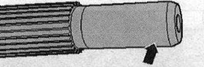
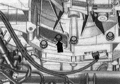
Aluminum bolts -2...10- can be used twice. Therefore, after the first use, mark such bolts with two notches "X" -arrow-.
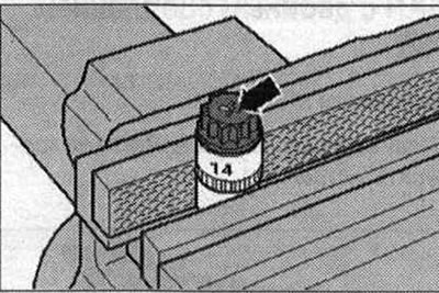
To avoid damaging the bolts when making notches, do not clamp them in a vice. Insert the bolt, as shown in the figure, into the 14 socket head using 1/2"-drive, which can then be secured in a vice. Tagged "X" Do not reuse bolts. Steel bolt -1 - can be used repeatedly.
Visitor comments