
Table of contents: Diagnostic procedure ↓ Decoding fault codes by channels ↓
Automatic air conditioning control panel (other control panel layout is possible)
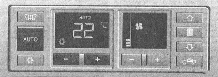
- To change the channel number up or down, press the "+" or "–" button respectively.
- To call up information in the selected channel, press the air recirculation mode button.
- To exit the code reading mode, press the AUTO button or turn off the ignition.
- 61 channels are provided. When diagnostic information is displayed, the K/V continues to operate in the last selected mode.
(The diagnostic codes of the air conditioner, read by the scanner from the diagnostic connector, are presented below)
Diagnostic procedure
1. Turn on the ignition or start the engine.
2. Press and hold the air recirculation button.
3. Press and hold the air supply button upward on the air distributor.
4. Release both buttons.
5. The channel number is displayed on the display screen (01c – first, 02c – second, etc.).
| Number diagnostic channel |
Display
|
| 1 | System failure – a fault code is displayed (decoding codes are presented below) |
| 2 | Temperature sensor reading under the ceiling trim (G86) |
| 3 | Temperature sensor reading in the instrument cluster area (G56) |
| 4 | Air intake temperature sensor reading (G89) |
| 5 | Front outside air temperature sensor reading (G17) |
| 6 | Outdoor air temperature sensor reading |
| 7 | Indication of the temperature sensor of the outside air supplied to the passenger compartment air (G109) |
| 8 | Temperature value in the area of the electric motor position sensor regulating valve drive (G92) |
| 9 | Temperature value in the area of the control valve |
| 10 | A certain, unchangeable value of temperature in a region regulating valve |
| 11 | Central control motor position sensor reading dampers (G112) |
| 12 | Required value of the central flap position |
| 13 | Indication of the position sensor of the electric motor of the damper drive switching the air supply direction (windshield blowing/air supply in footwells) (G114) |
| 14 | Required value of the direction change flap position air distribution |
| 15 | Air drive electric motor position sensor reading dampers (G113) |
| 16 | Required air damper position value |
| 17 | Vehicle speed (km/h) |
| 18 | Actual supply voltage of the heater fan (V) |
| 19 | Actual supply voltage of the heater fan (V) |
| 20 | Supply voltage K/V (V) |
| 21 | Number of voltage drops (excluding short-term surges) |
| 22 | Cyclically high pressure switch sensor reading refrigerant K/V (F118) |
| 23 | Refrigerant Pressure Switch Over-Reading Cycles K/V (F118) |
| 24 | Cycling of sensors-switches (without fluctuations) |
| 25 | Analog/digital form of the activation switch sensor readings kickdown mode |
| 26 | Analog/digital form of control reading coolant temperature lamps |
| 27 | Encoded value |
| 28 | Engine speed (мин⁻¹) |
| 29 | Compressor speed K/V (rpm x 1.28) |
| 30 | Software version |
| 31 | Checking the display (all segments should be highlighted) |
| 32 | Mixing flap position sensor failure counter |
| 33 | Central flap position sensor failure counter |
| 34 | Failure counter of the position sensor of the direction change flap air distribution |
| 35 | Air damper position sensor failure counter |
| 36 | Mixer Position Sensor Cold Stop Value dampers (G92) |
| 37 | Mixer Position Sensor Hot Stop Value dampers (G92) |
| 38 | Cold Stop Value of the Center Position Sensor dampers (G112) |
| 39 | Hot Stop Value of the Center Damper Position Sensor (G112) |
| 40 | Cold Stop Value of Shift Position Sensor air distribution directions (G114) |
| 41 | Shift Position Sensor Hot Stop Value air distribution directions (G114) |
| 42 | Cold Stop Value of Wastegate Position Sensor dampers (G113) |
| 43 | Wastegate Position Sensor Hot Stop Value (G113) |
| 44 | Vehicle cycle counter |
| 45 | Calculated temperature in the car interior (in numbers) |
| 46 | Calculated outside air temperature (filtered) |
| 47 | Outside air temperature (unfiltered,°C) |
| 48 | Outside air temperature (unfiltered, in numbers) |
| 49 | Speedometer/VSS Failure Counter |
| 50 | Parking time (in H min) |
| 51 | Engine coolant temperature,°C |
| 52 | Graphic Channel 1 - Refer to the fault code definitions below
NOTE: When channel 52 is selected, the display will initially show the following picture: "__ _". The K/V electrical output signals are identified by the lighting of certain signals on the display. |
| 53 | Graphic Channel 2 - Refer to the fault code definitions below
NOTE: When channel 53 is selected, the display will initially show the following picture: "__ _". The K/V electrical output signals are identified by the lighting of certain signals on the display. |
| 54 | Control parameters |
| 55 | Outdoor temperature in°C or°F depending on the selection of the A/C control head |
| 56 | Temperature sensor readings under the ceiling trim,°C (G86) |
| 57 | Temperature sensor readings under the instrument panel,°C (G56) |
| 58 | Air intake temperature sensor readings,°C (G89) |
| 59 | Front outside air temperature sensor readings, °C (G17) |
| 60 | Heater Fan Temperature Sensor Readings,°C (G109) |
| 61 | Software version (latest) |
Decoding fault codes by channels
Diagnostic channel 1
| Trouble Code (DTC) |
Possible reason for refusal
|
| 02.1 | Open circuit in the temperature sensor under the ceiling trim G86; default value for sensor failure: 128 |
| 02.2 | Short circuit in ceiling temperature sensor circuit g86 upholstery; You DTC 02.1 |
| 02.3 | Unstable contact failure in the temperature sensor circuit under the ceiling trim G86 |
| 02.4 | Unstable short H·m yknock in temperature sensor circuit under the ceiling trim G86 |
| 03.1 | Open circuit in the temperature sensor under the instrument panel G56; You DTC 02.1 |
| 03.2 | Short circuit in the temperature sensor circuit under the instrument panel shield G56; You DTC 02.1 |
| 03.3 | Unstable contact failure in the temperature sensor circuit under the instrument panel G56 |
| 03.4 | Unstable short H·m yknock in temperature sensor circuit under the instrument panel G56 |
| 04.1 | Open circuit in the air intake temperature sensor G89; if the sensor fails, the signal from the G17 sensor is used DTC 04.1 |
| 04.2 | Short H·m yk in the air intake temperature sensor circuit G89; U DTC 04.1 |
| 04.3 | Unstable contact failure in the temperature sensor circuit in the G89 air intake |
| 04.4 | Unstable short H·m yknock in temperature sensor circuit in the G89 air intake |
| 05.1 | Open circuit in the outside air temperature sensor G17; at if the sensor fails, the sensor signal G89-DTC 04.1 is used |
| 05.2 | Short H·m yk in the outside air temperature sensor circuit G17; U DTC 05.1 |
| 05.3 | Unstable contact failure in the temperature sensor circuit outside air G17; Default value when both sensors fail (G89 and G17): 128 |
| 05.4 | Unstable short H·m yknock in temperature sensor circuit outside air G17 |
| 06.1 | Open circuit in engine coolant temperature sensor (K/V) G110; If the sensor is faulty or not installed, the coolant temperature liquids are calculated; diagnostics are only possible at temperatures above 0°C (32°F) |
| 06.2 | Short circuit in coolant temperature sensor circuit engine fluids (E/F) G110; U DTC 06.1 |
| 06.3 | Unstable contact failure in the temperature sensor circuit engine Coolant (EC) G110 |
| 06.4 | Unstable short H·m yknock in temperature sensor circuit engine Coolant (EC) G110 |
| 07.1 | Open circuit in the heater fan temperature sensor G109;
Programmed correct value = 0 |
| 07.2 | Short H·m yk in fan temperature sensor circuit heater G109; You DTC 07.1 |
| 07.3 | Unstable contact failure in the temperature sensor circuit heater fan G109 |
| 07.4 | Unstable short H·m yknock in temperature sensor circuit heater fan G109 |
| 08.1 | Open circuit in the G92 mixing flap position sensor; Automatic control of the operation of the drive electric motor becomes impossible, manual adjustment required |
| 08.2 | Short H·m yknock in the mixing position sensor circuit g92 flaps; You DTC 08.1 |
| 08.3 | Unstable contact failure in the position sensor circuit mixing valve G92 |
| 08.4 | Unstable short H·m yknock in the position sensor circuit mixing valve G92 |
| 08.5 | Blocking the position sensor of the mixing flap G92; electric motor stuck, software tries to eliminate the cause of the blockage |
| 08.6 | Failure of the position sensor of the mixing flap G92 |
| 08.7 | Unstable blocking of the mixing flap position sensor G92 |
| 11.1 | Open circuit in the central flap position sensor G112; Automatic control of the operation of the drive electric motor becomes impossible, manual adjustment required |
| 11.2 | Short H·m yk in the central flap position sensor circuit G112; You DTC 11.1 |
| 11.3 | Unstable contact failure in the central position sensor circuit g112 flaps |
| 11.4 | Unstable short H·m yknock in the central position sensor circuit g112 flaps |
| 11.5 | Blocking the central flap position sensor G112; electric motor stuck, software tries to eliminate the cause of the blockage |
| 11.6 | Central flap position sensor G112 failure |
| 11.7 | Unstable blocking of the central flap position sensor G112 |
| 13.1 | Open circuit in the direction changeover flap position sensor air distribution G114; Automatic control of the drive operation electric motor becomes impossible, manual adjustment is required |
| 13.2 | Short H·m yk in the shift valve position sensor circuit air distribution directions G114; DTC 13.1 |
| 13.3 | Unstable contact failure in the throttle position sensor circuit switching the direction of air distribution G114 |
| 13.4 | Unstable short H·m yknock in the position sensor circuit air distribution direction switching flaps G114 |
| 13.5 | Direction Switch Flap Position Sensor Blocking air distribution G114; the electric motor is stuck, the software is trying eliminate the cause of the blockage |
| 13.6 | Failure of the direction change flap position sensor air distribution G114 |
| 13.7 | Unstable locking of the shift valve position sensor air distribution directions G114 |
| 15.1 | Open circuit in the wastegate position sensor G113; If the sensor fails, the software sets an emergency value |
| 15.2 | Short H·yk in the wastegate position sensor circuit G113; You DTC 15.1 |
| 15.3 | Unstable contact failure in the bypass position sensor circuit g113 flaps |
| 15.4 | Unstable short H·m yknock in the position sensor circuit bypass valve G113 |
| 15.5 | Blocking the wastegate position sensor G113; electric motor stuck, software tries to eliminate the cause of the blockage |
| 15.6 | Failure of the wastegate position sensor G113 |
| 15.7 | Unstable blocking of the wastegate position sensor G113 |
| 17.0 | Vehicle Speed Sensor VSS Failure |
| 18.1 | Constant incorrect supply voltage of the fresh air fan air |
| 18.3 | Periodically incorrect fan supply voltage fresh air |
| 20.1 | Constant incorrect supply voltage of the compressor K/V; The compressor only switches on if its supply voltage is maintained at a level not lower than 10.8V for at least 25 seconds |
| 20.3 | Periodically incorrect supply voltage of the compressor K/V; The compressor only turns on |
| 22.1 | Open circuit in the refrigerant high pressure switch sensor K/V F118; The compressor remains off until the switch sensor open |
| 22.3 | Unstable contact failure in the sensor-switch circuit high pressure refrigerant K/V F118 |
| 22.5 | Open circuit 120X in the high pressure sensor-switch circuit refrigerant K/V F118; compressor reactivation circuit, scanner operation VAG 1551 |
| 29.1 | Constant soft belt slippage |
| 29.2 | Constant hard belt slippage |
| 29.3 | Intermittent soft belt slippage |
| 29.4 | Intermittent hard belt slippage |
Graphic diagnostic channel 52
CAUTION: The situation described below occurs when the A/C compressor is switched off.
Display segments KV
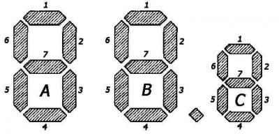
Segment group C. Segment burning indicates:
| 1 | Slippage or blocking, disconnection of 120x sensor– refrigerant high pressure switch |
| 2 | Engine speed dropped below 200-500 rpm |
| 3 | – |
| 4 | Engine speed exceeds 6000 rpm |
| 5 | – |
| 6 | – |
| 7 | The system is functioning normally1) |
Segment group B. Segment burning indicates:
| 1 | K/V is manually switched off (stand-by function is disabled) |
| 2 | Voltage too low |
| 3 | Kickdown mode activation switch sensor (via TCM, the compressor is switched off for a maximum of 12 seconds) |
| 4 | Coolant temperature indicator lamp switch sensor engine fluids |
| 5 | Low pressure switch sensor refrigerant K/V F73 |
| 6 | High pressure switch sensor refrigerant K/V F118 |
| 7 | The system is functioning normally1) |
1) If the system is functioning properly, segments C7, B7 and A7 should light simultaneously
Segment group A. Segment burning indicates:
| 1 | Economy mode (ECON) detected |
| 2 | The fact of shutdown has been revealed |
| 3 | The outside air temperature is too low |
| 4 | Engine management system (compressor remains off within 3 12 seconds) |
| 5 | The pressure remains elevated for more than 30 seconds |
| 6 | The air temperature sensor in the fan records the value less than – 3°C (27°F) |
| 7 | The system is functioning normally1) The dividing point is visible: the compressor is on The dividing point is not visible: the compressor is switched off |
1) If the system is functioning properly, segments C7, B7 and A7 should light simultaneously
Graphic diagnostic channel 53
CAUTION: The situation described below occurs when the A/C compressor is switched off.
Segment group C. Segment burning indicates:
| 1 | Fan for cabin temperature sensor |
| 2 | The recirculation mode selector valve is closed (closed-loop mode circulation) |
| 3 | Heat exchanger valve is closed |
| 4 | Bi-directional wiring harness |
| 5 | The A/C compressor is on |
| 6 | The first speed mode of the heater fan is on |
| 7 | The system is functioning normally1) |
Segment group B. Segment burning indicates:
| 1 | – |
| 2 | The air damper is open |
| 3 | Air damper closed d2 |
| 4 | – |
| 5 | The valve for switching the dispensing direction is in the position air supply to the foot wells |
| 6 | The valve for switching the dispensing direction is in the position supply air for blowing glass |
| 7 | The system is functioning normally1) |
Segment group A. Segment burning indicates:
| 1 | – |
| 2 | The central flap is in the air supply position to the instrument panel deflectors |
| 3 | The central flap is in the air supply position for blowing glass and into the footwells |
| 4 | – |
| 5 | The mixing valve is in the cold air supply position air |
| 6 | The mixing valve is in the warm water supply position air |
| 7 | The system is functioning normally1) |
1) If the system is functioning properly, segments C7, B7 and A7 should light simultaneously.