



Table of contents: Removal the climate control and… ↓ Installation ↓
On the Audi Q5, an additional cover "B" is provided for the control and display unit, the Climatronic control unit "J255" "A"

As a spare part, this trim "B" is already supplied with the double-sided adhesive tape "C" attached. If the trim "B" is to be reused when replacing the control and display unit, the Climatronic control unit "J255-A", remove the adhesive tape "C" from the trim "B". Clean the adhesive surface on the trim "B" as described in the instructions for use and processing of the adhesive tape. Then stick the trim "B" with a strip (size: 204 mm x 10 mm) double-sided adhesive tape "C" with a thickness of about 1.2 mm (eg adhesive tape D 438 515 A1). At the beginning of production, this cover "B" was secured with clamps "C" in the grooves "D" of the control and display unit, the Climatronic control unit "J255" "A". Later, the cover "B" was replaced by a version that was secured with suitable double-sided adhesive tape. This cover "B" no longer has the fasteners "F".
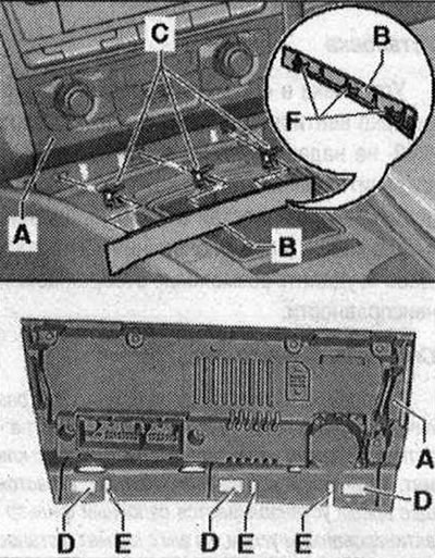
Since the grooves "D" and splines "E" cannot be made independently, only the cover "B" is offered as a spare part in a version that is attached with double-sided adhesive tape to the control and indicator unit, the Climatronic control unit "J255" "A".
Removal the climate control and indication unit, installation (used Climatronic "J255")
Instructions. Both versions ("Basis" or "Komfort") of the climate control and indicator unit, installation, Climatronic control unit "J255" are removed and installed in the same way.
Query the coding and adaptation of the climate control and display unit, installation, Climatronic control unit "J255" via the "Control unit replacement" function of the guided fault finding (if it is necessary to replace the climate control and display unit, installation, Climatronic control unit "J255"). To avoid damage to the center console and the air conditioning control and display unit, Climatronic control unit "J255", do not use force when removing. Do not damage the surface of the center console when removing (cover it if necessary). Switch off the ignition. Insert hook "3438" "B", as shown in the figure, into one of the holes "C" or "D" of the climate control and display unit, installation, Climatronic control unit "J255--A".
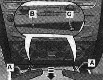
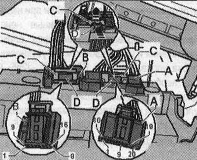
Carefully remove the air conditioning control and display unit, Climatronic control unit "J255", "in the direction of the arrow" from the center console. Used and climate control, installation, Climatronic control unit "J255" is held in the center console with clamps (left and right). Disconnect the plug connectors of the air conditioning control and display unit, Climatronic control unit "J255". Disconnect the fuse of connection "C" of plugs "A" and "B" by pulling it in the direction of the arrow "arrow". Press the lock "D" to the plug "arrow" and remove plugs "A" and "B".
Installation
Installation in reverse order: When replacing the climate control and display unit, installation, control unit for Climatronic "J255", special attention must be paid to strict compliance. Install the cover on the control and display unit. Clean the adhesive surface "D" on the control and display unit "A" with, for example, cleaner D 009 401 04. Install the control and display unit "A".
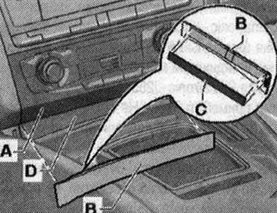
As a spare part, this trim "B" is already supplied with the double-sided adhesive tape "O" attached. If the trim "B" is to be reused when replacing the control and display unit, the Climatronic control unit "J255-A", remove the adhesive tape "0" from the trim "B". Clean the adhesive surface on the trim "B" as described in the instructions for use and processing of the adhesive tape. Then stick the trim "B" with a strip (size: 204 mm x 10 mm) double-sided adhesive tape "O" with a thickness of about 1.2 mm (eg adhesive tape D 438 515 A1). Install cover "B" with adhesive tape "C" to the adhesive surface "D" of the control and indicator unit "A" and align cover "B". Press cover "B" to the adhesive surface "D". After replacing / removing the air conditioner control and indicator unit, Climatronic control unit "J255", it is necessary to carry out the following work: recode the climate control and indicator unit, settings, control unit for Climatronic "J255" (or check the encoding). Perform basic setup of the climate control and display unit, installation, control unit for Climatronic "J255". Interrogate the fault memory of the climate control and display module, installation, control unit Climatronic "J255" (eliminate the cause of the displayed faults) and, if necessary, erase the displayed faults. Check the adaptation of the control and display unit for climate control, installation, control unit for Climatronic "J255" and correct it if necessary. Perform diagnostics of the actuators of the control and display unit for climate control, installation, control unit for Climatronic "J255" (depending on the specific complaint).