
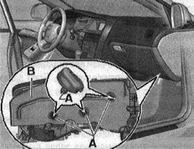
Release screws -A-. Disconnect the air duct to the right front panel deflector from the front panel cross member (don't take off).
Air duct from air channel -B- to the right front panel deflector is secured with two bolts; to loosen it, remove only the bolt that is screwed from below into the front panel cross member and is accessible. Remove air duct -B- to front panel vent on right (on the front passenger side).
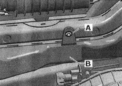
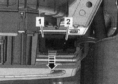
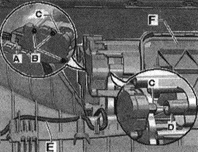
Remove A-pillar trim -C- and mounting -B-. Disconnect plug -A- from fresh air blower control unit -L 26-. If equipped, remove headlight range control control unit -J431- -1- (Or control unit for adaptive lighting and headlight range control -J745-) and corresponding mounting frames.
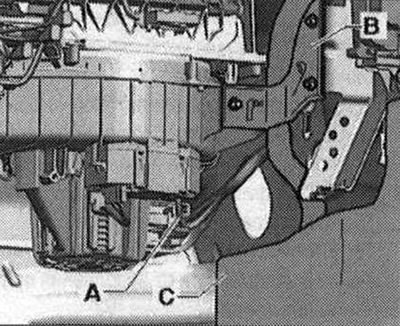
Remove fresh air fan -V2-. The air intake duct in the air conditioner can also be removed and installed with the supply fan -V2- installed; due to the limited installation space, it is still advisable to remove -V2- (more freedom of movement will be achieved when removing and installing the air intake duct). Remove cables -A- from the mounting points of the air intake duct. Open fastening -C- (between the air conditioner and the air intake box-B-), e.g. using a screwdriver -D- (lift slightly and pull in the direction of the arrow).
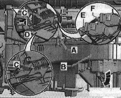
Pull out the air intake duct -B- (after opening the fastening -C-) right down (in the direction of the arrow). Mark connectors to air intake flap control motor -V71-E- and -F- to air recirculation flap control motor -V113- (so as not to be confused with other plugs) and disconnect them from the servos.
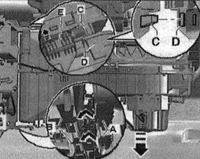
Remove the upper tongue of the air conditioner -E- from the mounting of the air intake duct -D-. Release both lower mounting points between air conditioner -B- and air intake duct -A-. Remove the air intake box.
Installation
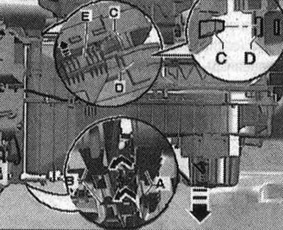
Installation is carried out in the reverse order; in this case, it is necessary to check and, if necessary, clean the evaporator -A- and the air duct in the air conditioner to the evaporator -B-. Check and, if necessary, clean the cabin filter and the air duct in the air intake duct to the air conditioner -C-. Check the integrity of the round groove on the air conditioner -D- and the round chamfer on the air intake duct -E-.
If a groove or chamfer is damaged, fill the damaged area, for example, with silicone sealant D176 001 AZ. Because When the climate of the installation is operating, air may pass through here, which will cause noise. Before installing the air intake duct -C-, check the integrity of the seal on the outside air intake shaft -A-. If necessary, replace damaged seal. Check the position of the lock; only if the lock -B- is in the position corresponding to the figure, you can connect the air intake duct -C- and the air conditioner -D-.
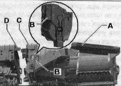
Connect the connectors to the air intake flap actuator motor -V71- -E- and to the recirculation flap actuator motor -V113- -F- in accordance with the markings. Insert both lower tabs of the air intake duct -A- into the mounting points of the air conditioner -B-. Lift the air intake duct on the right side until the upper tongue of the air conditioner -C- fits into the mount of the air intake duct -D-, then press both elements together. When assembling the air intake duct, be careful when handling the air conditioner and installation and do not use great force. If the air intake duct is connected to the climate control system using force, then the lower brackets of the air intake duct -A- remain deformed. Due to deformation of the air intake duct brackets -A-, a whistling sound may occur during climate control operation. installation due to minor leaks in connecting points. If the lock -E- moves forward during installation, it will not be possible to compress both elements. When installing, make sure that you do not pinch other elements and that the chamfer at the air intake duct is completely seated in the groove at the air conditioner. Move the lock-C- against the arrow (and thereby secure the air conditioner to the air intake duct -B-). Install cables -A- into the mounting points of the air intake duct.
When laying cables, make sure that they do not touch the moving parts of the actuator motors. All removed elements are installed in reverse order. Perform basic setup and diagnostics of climate control actuators and settings. On this vehicle, the actuator electric motors have an electronic part; the new electric motor stores its position on the air conditioner in memory only during the basic setting, after which it is ready to execute commands from the climate control and display unit, settings, Climatronic control unit -J255- (currently all electric motors are identical). During basic setup, the actuator motors are assigned and programmed according to the distribution in the series connection. If this sequence does not match the specified parameters, the servos will store incorrect information and the dampers will not be controlled correctly (circuit diagram of climate control. installations). If you are not sure that both control motors, the air intake flap control motor -V71- and the recirculation flap control motor -V113-, are correctly connected to the wiring. You can check the control using the function Diagnosis of climate control elements. installations", when the glove box is removed, the recirculation flap -F- is visible.
Visitor comments