
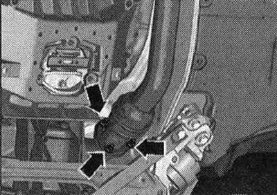
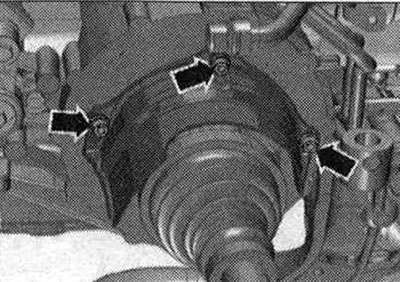
Unscrew the exhaust pipe nuts -arrows-.
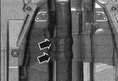
Disconnect the exhaust system by loosening the clamp -arrows- and remove the exhaust pipe.
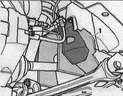
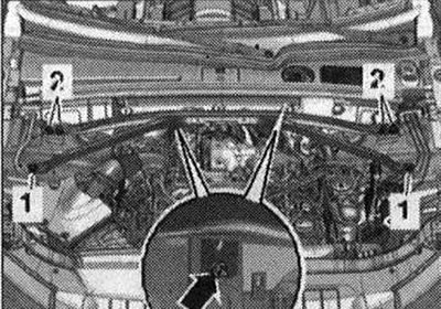
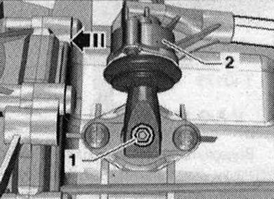
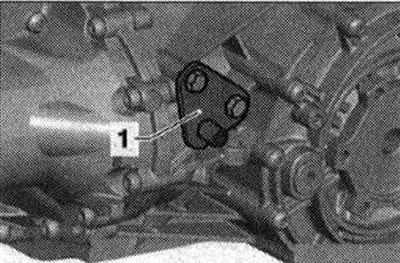
Unscrew bolt -1- and -2- and remove mounting bracket.
Remove the stretch.
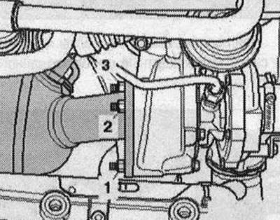
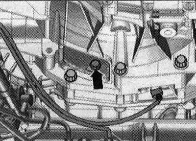
Remove the air housing. filter. Unscrew the nuts -1,2,3- of the turbocharger and tie up the filter.
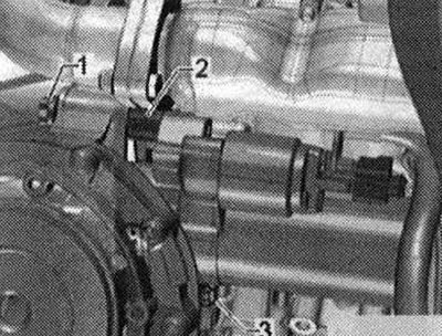
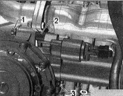
Remove bolts -1- and -3-. -Pos. 2- do not take into account.
Disconnect wire -A- from gearbox using lever -80 - 200- and disconnect connector -C-.

Unscrew the bolts -3...6- of the engine/gearbox connection. Remove starter bolt -1-. Remove spacer sleeve -2- between starter and gearbox.
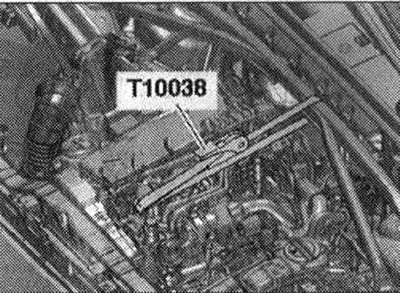
Install the brace and attach it using a belt -T10038- to the engine eye, as shown in fig. Tighten the tension belt.
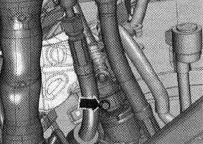
Risk of damage to the Airbag coil spring. Disconnect the universal joint from the steering gear only with the front wheels mounted straight. Do not change the position of the steering wheel or steering gear again; to do this, if necessary, secure the steering wheel with adhesive tape. Remove bolt -arrow- from universal joint. Press the steering gear universal joint out and push it all the way up.
Unscrew the nut -1- of the hydraulic oil pressure line of the power steering. Risk of damage to chassis parts. If the subframe, steering gear or subframe spacer are not installed properly, the vehicle must not be placed on wheels! Using a subframe or subframe cross as a vehicle support (for example, when lifting with a jack or similar device) unacceptable! Unscrew the bolts -arrows- and remove the subframe spacer.

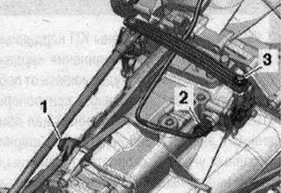
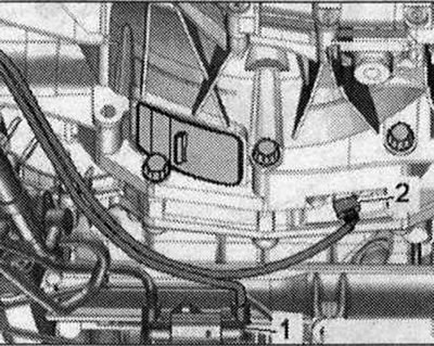
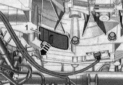
Disconnect connector -2- from engine speed sender -G28- and free electrical connection. wire from fasteners. -Pos. 1- do not take into account.
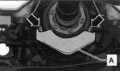
If present, remove bolts -arrows- and remove heat shield for propeller shaft -A-.
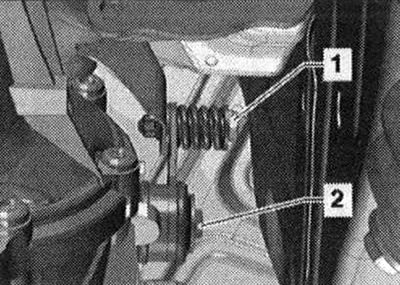
Secure the propeller shaft from turning using the support -T10172- and adapter -T10172/5-. On vehicles with a driveshaft inserted from the gearbox side, hold the rear final drive in the same way. Engage 6th gear, to do this, remove the shift shaft -1- and shift the gearbox lever -2- forward in the -direction of the arrow-.
Remove trim -1- under gearbox -arrow-.
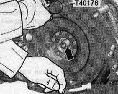
Unscrew the 3 bolts -arrow- of the driven disc; to do this, rotate the clutch module through 120°in the direction of engine rotation.
The propeller shaft is screwed on the gearbox side: Unscrew the bolts connecting the propeller shaft and the gearbox, while holding it against turning using the counterhold -T10172- with -T10172/5-. Move the cardan shaft to the rear main gear; constant velocity joints are movable in the axial direction. Tie the driveshaft to the side.
The propeller shaft inserted from the gearbox side: Remove the propeller shaft.
All
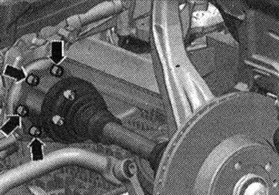
Unscrew the bolts -arrows- and remove the heat insulation shield for the right drive shaft.
Unscrew the left and right drive shafts from the gearbox flange shafts.
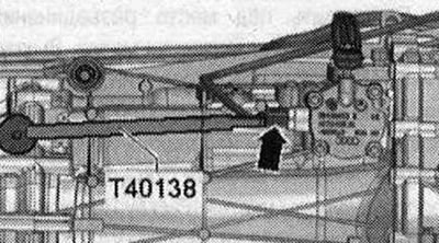
Disconnect email Plug connection -arrow-for gear detection sensor -F208- using a puller -T40138- and release the electrical cable.
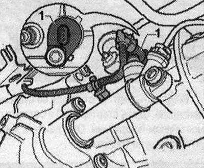
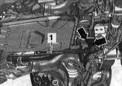
Vehicles with system «start-stop»: Disconnect email. Plug connection for gearbox neutral position sensor -G701 --1- and release the cable.
All
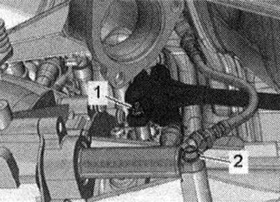
Unscrew the screw -2- and remove the clutch slave cylinder from the gearbox, removing the tube from the bracket. Tie the slave cylinder to the side of the engine. Risk of damage to the clutch slave cylinder. Do not press the clutch pedal after removing the clutch slave cylinder. Unscrew nut-1-.
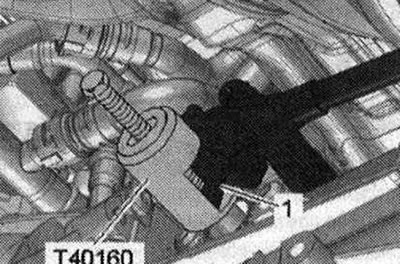
Risk of damage to the shift shaft in the gearbox. Do not press the shift lever -1 - with a pry bar or knock it down with a hammer. Remove the gearshift lever only using a puller -T40160-. Install puller -T40160- and remove shift lever -1-.
Place a device for pumping out oil under the disconnection point. Unscrew bolts -arrows-, disconnect hydraulic line -1- from steering gear and place to one side. To prevent contamination from entering, seal open lines and connections with clean plugs from the engine plug set -VAS 6122-.
Unscrew the starter bolt -3- from the engine side. Remove the starter from the gearbox and leave it in its installation position. There is no need to disconnect the starter cables.
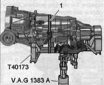
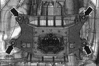
Place engine and gearbox lift with gearbox mount -T40173- under gearbox and secure with tensioning belt -1- as shown in the illustration.
Remove the remaining bolts -7...9- of the engine/gearbox connection. Unscrew the bolts -arrows- of the tunnel cross member. Press the gearbox away from the engine and carefully lower it using the tilt lever. When lowering, check that the cable is not pinched on the top side of the gearbox. When lowering, make sure the drive shafts move freely.
When replacing a removed gearbox, the following parts must be replaced with the new gearbox. Holder -1- for exhaust system mounting strip.
If necessary, remove the clutch module.
Visitor comments