
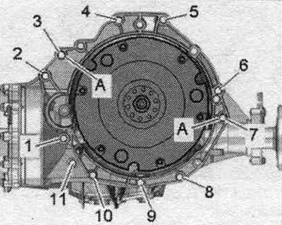
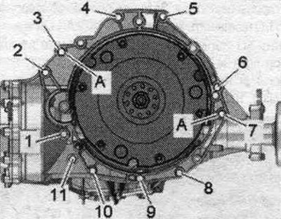
Check the presence of centering bushings "A" for the engine and gearbox in the cylinder block; insert the bushings if necessary. Check the aluminum bolts "2...11" for fastening the engine to the gearbox for suitability for reuse and, if necessary, apply markings.
Install the clutch module if necessary.
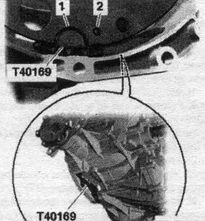
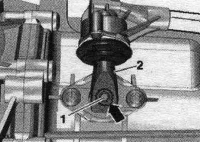
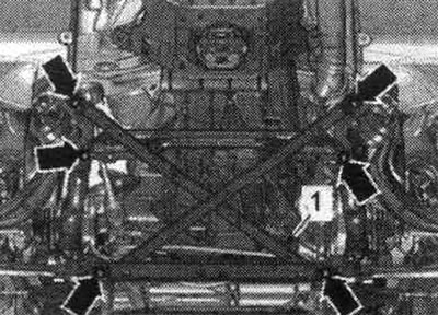
Install the gearbox on the gearbox bracket "T40173" and secure with harness "1", as shown in the figure. Before connecting the engine and gearbox, carry out the following preparatory actions. Install the auxiliary mounting device "T40169" from below into the gearbox housing and into the clutch module, as shown in the figure. Mounting tool "T40169" should fit into semicircular groove "1" and additionally into inspection hole "2." There is only one inspection hole around the perimeter; rotate the clutch module accordingly. Insert mounting bolts. "T40169" device into the hole on the gearbox housing.
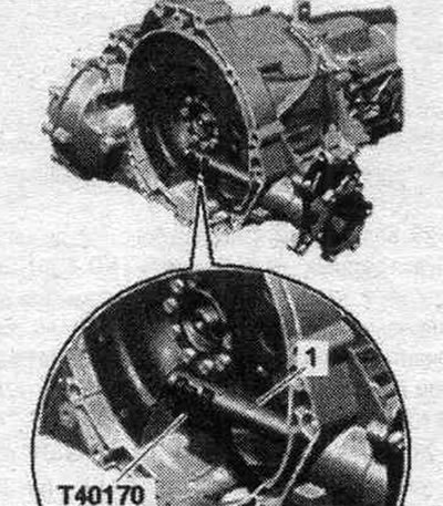
Install the "T40170" transport protection from below under the gearbox housing and attach it to the shaft with flange "1".
Raise the gearbox so that the clutch slave cylinder can be installed. Tighten bolt "2".

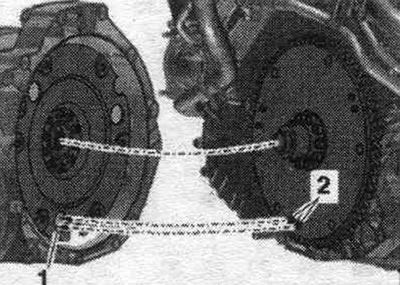
The next step is only necessary if the driven disc with locking pin "2" is installed. Additionally, align the position of the driven disc in relation to the clutch module so that locking pins "2" (if available) on the driven disk could enter the large holes "1" on the clutch module. If the retaining pins of the driven disk "2" do not enter the holes of the clutch module "1", this can lead to serious problems in the operation of the clutch.
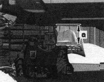
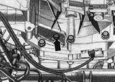
Attach the gearbox to the engine and tighten bolts "3...11". Install the starter and tighten bolt "1" on the engine side. Tighten bolt "2" on the gearbox side. Disconnect spindle "10-222 A/11". Raise the gearbox with a powertrain lift until gap "a" between the tunnel crossmember and the body is reached. Size "a" = approx. 100 mm.
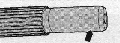
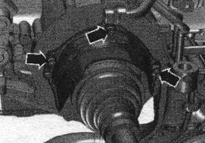
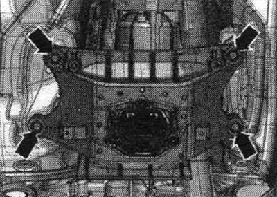
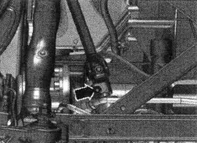
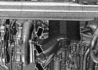
Bolt the left and right drive shafts to the transmission flange shafts. Install the drive shaft heat shield and tighten the "arrow" bolts to 23 Nm.
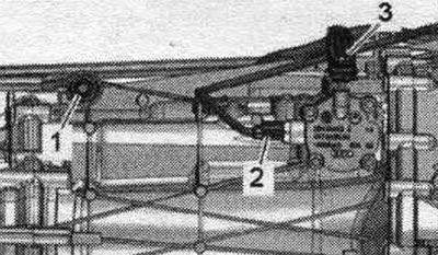
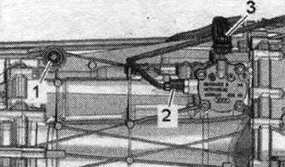
Tighten the shift fork rod "1". Connect the connector "2" of the gear position sensor "F208". Align the connecting rod "3" as shown in the figure.
Install gearshift lever "2" as follows: gearshift lever "2" can be installed on shift shaft "1" in only one position (the notch in the gear ring "arrow"). Tighten gearshift lever "2".
Continue raising the gearbox and tighten the tunnel crossmember arrow bolts. Remove the tilter with the mounting bracket "T0173" from under the gearbox.
Tightening sequence - clutch module to driven disc
Remove mounting tool "T40169" and transport protection "T40170". Engage 6th gear by removing shift shaft "1" and shifting gearshift lever "2" forward in the direction of the arrow.
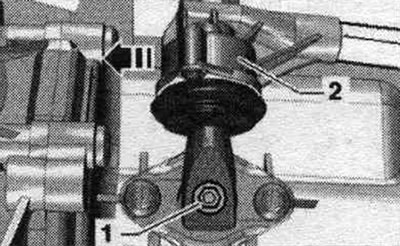
The next stage of work is absolutely necessary to ensure uniform contact with the driven disk without distortion. Rotate both fronts. wheels in one direction so that the clutch module makes 1 full revolution. The inspection hole "arrow" should be visible again in the recess of the gearbox housing.
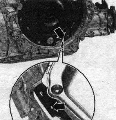
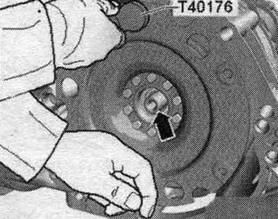
Tighten the clutch module bolts to the driven disc as follows. Use only new screws. Tighten the bolts with a 16 mm ring spanner "VAG 1332/14". Screw in the first bolt "arrow" all the way (2 Nm). Rotate the module/driven disk with the 2 front wheels 180°. Now screw in the 2nd bolt and tighten to the specified torque.
Next, screw in the remaining bolts connecting the clutch module to the driven disk in sequence and immediately tighten them (even a bolt that has just been screwed in) specified tightening torque. Installation in reverse order. Screw the cardan joint "arrow" to the steering gear.
Screw the connecting rod "3" from above, through the removed front wall of the water drainage box. "Pos. 2" and "3" do not take into account.
Install the particulate filter and exhaust pipe. Align the system. exhaust gas release without mechanical stress. Remove the end wall of the radiator tank. Install a stretcher.
Install the subframe spacer crosspiece. Check the oil level in the manual transmission. Install sound insulation. Consider the measures required after disconnecting the battery.
Tightening torques (Nm)
| Bolts and nuts | M6 | 9 |
| M7 | 15 | |
| M8 | 20 | |
| M10 | 40 | |
| M12 | 65 |
Mounting the engine to the manual transmission
| Pos. | Bolt | Nm |
| 1 (1) | M10 x 50 (2) | 65 |
| 2 (1) | M12 x 100 (3) | 30 + 90° |
| 3...6 | M12 x 100 (3) | 30 + 90° |
| 7 | M12 x 125 (3) | 30 + 90° |
| 8, 11 | M10 x 60 (3) | 15 + 90° |
| 9, 10 | M10 x 95 (3) | 15 + 90° |
| A | Centering bushings | |
(1) Additionally secures the starter.
(2) The steel bolt is not replaceable.
(3) Check the reusability of aluminum bolts and replace if necessary.