
Table of contents: Pressure regulator ↓ Checking the throttle potentiometer ↓ Checking injection nozzles ↓ Checking temperature sensors ↓ Starting valve ↓ Lambda probe ↓ Air flow meter ↓ Idle speed stabilization ↓
Pressure regulator
Pressure measurements require the presence of an appropriate pressure gauge (V.A.G. 1318) with shut-off valve and adapter. In idle mode, the fuel supply pressure should be approximately 2.5 bar, with the vacuum hose removed from the pressure regulator, it should increase to 3 bar.
Checking the throttle potentiometer
Disconnect the throttle potentiometer plug.
Connect an ohmmeter to contacts 1 and 2.
Move the throttle valve, while monitoring the ohmmeter. The resistance should change evenly.
Checking injection nozzles
For electrical testing you will need an LED voltmeter.
Checking the power supply: remove the plugs on the injection nozzles one by one.
Connect the voltmeter to the contacts of the removed plug.
The assistant must start the engine.
The LEDs should flicker, otherwise there is a defect in the wiring to the injectors or the control unit itself is faulty.
Checking the injectors: remove all the plugs on the injection injectors.
Connect an ohmmeter to both plug contacts of the first injection nozzle.
Standard value: 15-20 Ohm.
Repeat the test on other injectors.
More detailed check (type of jet/tightness)
Remove injection nozzles together with the distributor pipe - description of work see below in this chapter.
However, the wire ends must remain on and the fuel lines connected.
On the left in the cooling system pipe, remove the plugs of the starting valve and temperature sensor.
Direct the injection nozzles into four measuring containers.
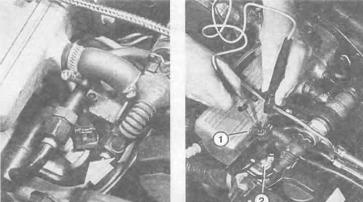
Left: The injection nozzles (arrow) are located on the right side of the cylinder head in the direction of travel in the intake manifold.
Right: The illustration shows the connector plug (1) removed from the injection nozzle (2). Using the LED voltmeter, you can check whether the power supply to the injection nozzles is OK.
Now the assistant should turn the starter for a few seconds: the injection stream should be the same for all four nozzles. In this case, the appearance of the stream is normal.
Remove the central plug of the injection nozzles in the cable shaft.
Turn off the ignition and turn it on for 5 seconds: no more than two drops should come out of each injector. In this case, the injectors are sealed properly.
Checking temperature sensors
Intake Air Temperature Sensor: Disconnect the 4-pin connector on top of the air flow meter.
Connect an ohmmeter to both external plug contacts.
Coolant Temperature Sensor: Disconnect the blue plug from the sensor in the coolant system filler neck.
Connect an ohmmeter to the sensor plug contacts.
Both sensors: take resistance readings.
Check the diagram to see if the data for the sensor resistance is correct (air and coolant temperatures) at the time of measurement within the curve.
If so, then the sensors are OK.
Starting valve
Disconnect the plugs from all injection nozzles.
Power supply: Remove the wire end on the starting valve.
Connect the LED voltmeter with auxiliary wiring to the plug.
Disconnect the plug from the coolant temperature sensor.
The assistant should turn the engine over with the starter, and the LED should flash for 1-4 seconds.
If this does not happen, then the wiring is interrupted or the Digifant injection system control unit is faulty.
Checking the operation: the injector plugs remain disconnected.
Unscrew the starting valve, the wire ends and fuel lines remain connected.
Disconnect the plug from the coolant temperature sensor.
Direct the starting valve into some container.
Have an assistant crank the engine with the starter.
Within 1-4 seconds the valve should inject gasoline in a uniform stream.
Wipe the valve clean to check for leaks,
No gasoline should come out of it within a minute, and the starting valve should not appear wet from fuel either.
Lambda probe
This test requires a CO measuring device, so a visit to a workshop may be necessary. The exhaust system must be in good working order and the lambda probe must be powered for proper testing (are the fuses ok?).
Warm up the engine.
Connect the device to measure CO content.
Start the engine and let it idle for at least 2 minutes.
Increase the rotation speed to 2000 rpm.
Record the CO content.
On the throttle body, remove the vacuum hose of the pressure regulator and close the tube with your finger.
The CO content should increase for a short time and then fall back to the value already measured
If the CO value does not change, disconnect the plug connection to the lambda probe.
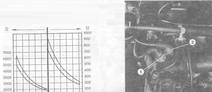
This diagram is for the coolant temperature sensor ("1" in the illustration on the left). It shows what resistance the sensor should have at a certain coolant temperature. Position "2" indicates the coolant temperature sensor and the temperature reading (see also the chapter "Instruments and devices").
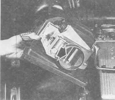
The shut-off valve (arrow), visible in the air opening of the air flow meter, should move slightly. The electrical check of the air flow meter is carried out at the connecting contacts, which in this illustration are visible at the top of the air flow meter housing.
Connect the wire to the contact on the plug (to the control unit) alternately with the positive and negative terminals of the battery.
If the CO indicator changes during this check, then the lambda probe is faulty.
If the CO content value remains unchanged, then you need to check the wiring to the control unit.
If there are no faults here, then the control unit is faulty.
Air flow meter
Remove the wire tip on the air flow meter.
The numbering of the contact tongues when viewed from above goes from left to right from 1 to 4.
Intake air temperature sensor: check the serviceability of the sensors at contacts 1 and 4, as described in the paragraph "Checking the temperature sensors".
Potentiometer: connect an ohmmeter between middle contacts 2 and 3.
Move the shut-off valve while observing the ohmmeter.
The resistance must change.
Connect an ohmmeter between contacts 3 and 4.
The resistance value should be between 0.5 and 1 kOhm (constant).
If you get different readings during the measurement, you need to replace the air flow meter.
Idle speed stabilization
Turn on the ignition - the valve should produce a slight humming sound. In addition, you can feel its slight vibration.
Otherwise, you should check the fuses.
If all fuses are OK, remove the plug on the idle speed stabilization valve. Using a diode test lamp, check for power in the plug at the contact of the black and blue wire (with ignition on). To do this, connect the other contact of the diode control lamp to ground.
If the light comes on, the valve's power supply is OK. Therefore, you need to check the valve itself:
Connect an ohmmeter and check the resistance at the valve plug contacts.
If the valve is working properly, the resistance reading should be 2-10 Ohms.
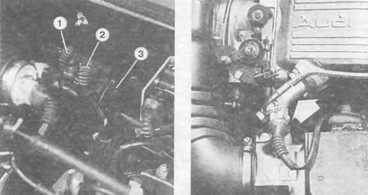
Left: Plug connection on the rear wall of the engine compartment. Designation:
1 - plug connection of the detonation sensor;
2 — plug connection for lambda probe heating;
3 — plug connection of the lambda probe signal.
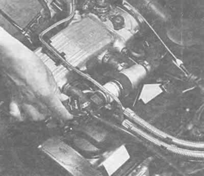
Right: The fuel start valve (arrow) is located in an easily accessible location at the rear right of the intake manifold.
In the illustration, the idle speed control valve plug (arrow) has been removed in order to check the valve and the wiring to it (see text).
If the standard value is not achieved, replace the valve.
If the resistance is correct, the cause of the malfunction should be sought in a break in the wiring or a defect in the Digifant injection system control unit.
To check the regulation, the control current is measured. For this, the workshop uses a device for interrogating the memory of the VAG 1551 fault memory; measuring with improvised means does not make sense.
(Information obtained from this resource AUDIMANUAL.RU)