
Table of contents: Control unit ↓ Throttle valve ↓ Throttle potentiometer ↓ Pressure regulator ↓ Nozzles ↓ Incoming air temperature sensor ↓ Coolant temperature sensor ↓ Air flow meter ↓ Fuel starter valve ↓ Idle speed control valve ↓
Control unit
The control unit receives the following types of information via the multi-pin plug from:
Starter from terminal 50 - about the beginning and end of the starting process.
Throttle potentiometer - current throttle position.
Hall sensor in the ignition distributor - about the engine crankshaft speed.
Lambda probe in the catalytic converter - about the content of residual oxygen in the exhaust gases.
Potentiometer in the air flow meter - about the position of the pressure relief valve (admitted air).
Intake air temperature sensor in the air flow meter.
Coolant temperature sensor in the cooling system pipe.
Knock sensor on the cylinder block for "knock" combustion, see also chapter "Ignition system".
Based on the speed and load information, the control unit calculates the duration of the opening of the electromagnetic injection nozzles, which are actuated by an electromagnet, and thus the injected fuel quantity. For this purpose, the control unit has injection characteristics and additionally ignition characteristics at its disposal. These characteristics represent a data file for all possible operating situations of the engine and the corresponding fuel quantities and ignition timings. The control unit can change these values after receiving so-called correction signals.
Throttle valve
Two throttle valves are located in the pipe in the intake manifold. The smaller of these valves is connected by a cable to the gas pedal in the cabin. It controls the flow of intake air into the engine. If the accelerator pedal is pressed harder, then the rod opens the second, larger valve; in the full "gas" position, both valves are open.
Throttle potentiometer
The throttle potentiometer covers the current throttle position from "idle" (throttle valve closed) to "full load" (throttle fully open). Based on its information, idle speed stabilization is activated, fuel supply is stopped in forced idle mode, or the fuel mixture is enriched when the throttle valve is fully opened.
Pressure regulator
It is located in front of the fuel distributor and regulates the fuel supply pressure to the injection nozzles. To do this, it receives information about the vacuum state in the intake manifold. In idle mode, with the throttle valve closed and high vacuum, it maintains a lower pressure. When the vacuum decreases under greater engine load, the pressure regulator increases the fuel supply pressure. The fuel pump supplies fuel with a higher operating pressure, but thanks to the pressure regulator, the return of gasoline to the fuel tank increases or, if necessary, decreases accordingly.
Nozzles
With each rotation of the crankshaft, they inject gasoline into the injection channel in front of the intake valve of the corresponding cylinder - the duration of this process is determined by the control unit. The corresponding cylinder receives one portion as a reserve, and the second, when the intake valve is open, directly into the combustion chamber:
Incoming air temperature sensor
It is located on the side of the air flow meter and can thus accurately determine the temperature of the incoming air. The temperature of the incoming air enters the control unit in the form of a resistance value. This value is needed for optimal fuel dosing.
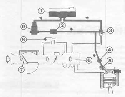
This illustration shows a schematic of the Digifant injection system with its components. The air path is shown by white arrows, the fuel supply is shown in red. The numbers indicate:
1 - fuel tank;
2 - fuel filter;
3 - pressure regulator;
4 — fuel distributor;
5 — nozzle;
6 — intake manifold;
7 — air flow meter;
8 — idle speed stabilization valve;
9 — fuel pump.
Coolant temperature sensor
The coolant temperature is necessary to control many injection functions. Information about the coolant temperature is also supplied to the control unit in the form of a resistance value. The control unit calculates the required injection duration, which is between two and eight milliseconds when the engine is warmed up to operating temperature. This value can increase by up to 70% if the coolant temperature reaches -25°C.
Air flow meter
The air required for combustion, supplied by the air filter, is more or less (depending on the amount injected) pushes aside the valve shutter in the air flow meter, while the damping valve connected to the valve shutter prevents the valve shutter from oscillating. The potentiometer sends a voltage signal to the control unit depending on the position of the valve shutter: high voltage when fully open and with a large amount of air, low voltage when slightly open.
Fuel starter valve
This electromagnetically driven injection nozzle injects additional fuel into the injection manifold for 1-4 seconds, depending on the engine temperature at start-up. The injection duration is determined by the Digifant injection system control unit.
Idle speed control valve
During the warm-up phase, when the power steering is turned fully, when the air conditioner is running or when the automatic transmission stage is engaged, this valve releases an additional air channel, thereby bypassing the throttle valve. Increased air exchange in the direction of the intake manifold simultaneously leads to increased fuel supply. The idle speed stabilization valve is also used in the forced idle mode. It allows the required amount of air to flow when the throttle valve is closed.
(The article is a reprint of material from «audimanual.ru»)