Repair Chevrolet Repair Toyota Repair Honda Repair AvtoVAZ Repair Mercedes-Benz Repair BMW Repair Opel
Home  |  Contacts  |  Sitemap  |    
English Русский
Български
Беларускі
Український
Српски
Hrvatski
Română
Polski
Slovenský
Magyar
AudiManual.ru


  • AUDI 80
  • AUDI 100
  • AUDI A3
  • AUDI A4
  • AUDI A6
  • AUDI A8
  • AUDI Q
  • OTHER
  • ARTICLES
C4 (1990-1994) C4 (1990-1994, petrol) C3 (1982-1990) C3 (1982-1990, petrol) C3 (1982-1990, diesel)

Checking the control unit (Audi 100 C3)

  • Home
  • Audi 100
  • C3 (1982-1990)
  • Power unit
  • Electronic ignition system
  • Checking the control unit
            0
Table of contents: Checking the supply voltage of the… ↓ Checking the output signal to the… ↓ Checking the output signal to the… ↓ Checking the output signal to the… ↓ Checking the output signal of the… ↓

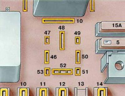
Socket "10" contact numbers on the relay and fuse box board


Socket «10» contact numbers on the relay and fuse box board


Checking the supply voltage of the unit


1. Disconnect the connector block with wires from the block.

2. Turn on the ignition and measure the voltage between contacts "35" and "18", then between "35" and "9". The voltage should be about 12 V. Turn off the ignition.

3. On a car with an automatic transmission, connect a voltmeter to terminals "9" and "32". Turn on the ignition and press the brake pedal. The voltage should be about 12 V. If the voltage is different, there may be a break in the wiring or a faulty brake pedal position sensor.

Checking the output signal to the fuel pump relay


1. Remove the fuel pump relay from its socket in the relay and fuse box.

2. Connect a voltmeter to contacts "46" and "47". Turn the crankshaft with the starter, the voltage should be about 9.5 V. Turn off the ignition. If the voltage differs from the specified, connect the voltmeter to contact "46" and "ground" and turn on the ignition. The voltage should be about 12 V. If the voltage differs from the specified, there is a break in the wiring.


3. Disconnect the connector block with wires from the control unit.

4. Connect the ohmmeter to contacts "47" and contact "21" of the control unit connector. The device should show zero, otherwise the wiring is damaged. If the wiring is not damaged, the control unit is faulty and must be replaced.

Checking the output signal to the engine braking valve


(only on vehicles with manual transmission)

1. Warm up the engine, the coolant temperature should be at least +50°C.

2. Disconnect the connecting block with wires from the valve.

3. Connect a voltmeter to the connector terminals. Start the engine and rev it up to 2000 rpm. Close the throttle valve, the voltmeter should show a voltage of approximately 12 V.

3. Connect a voltmeter to the connector terminals. Start the engine and rev it up to 2000 rpm.…


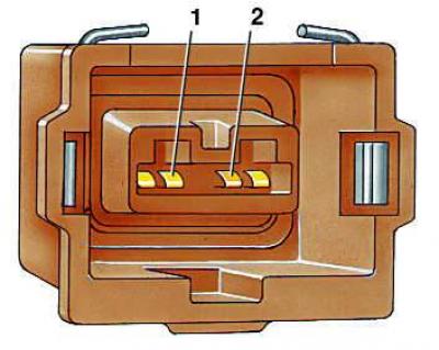
4. If the voltmeter readings differ, you need to check the wiring from the control unit to the valve. To do this, connect the ohmmeter to contact "2" of the valve block (for cars manufactured before 1985, connect the ohmmeter to contact "1") and contact "14".

5. The ohmmeter should show zero, otherwise the wiring is damaged. If the wiring is not damaged, and the ohmmeter shows some resistance, replace the control unit.


Checking the output signal to the bypass valve


The test is carried out on a warm engine with a coolant temperature of at least +50°C.

1. Start the engine and let it idle.

2. Manually turn on the full throttle switch and check by ear for the operation of the bypass valve.

3. If you do not hear the valve operate, turn off the engine and disconnect the connector block with wires from the valve.

3. If you do not hear the valve operate, turn off the engine and disconnect the connector block…


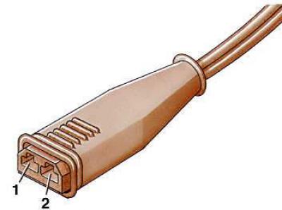
4. Connect the voltmeter to contacts "1" and "2". If the voltmeter shows a voltage of about 12 V, replace the valve. If the voltage differs from the specified one, connect the voltmeter to contact "2" and "ground".

5. Turn on the ignition, the voltmeter should show 12 V, otherwise you need to check the wires going to the valve block. To do this, connect the ohmmeter to contact "2" of the block and to contact "8" of the control unit block. The ohmmeter should show zero. If the ohmmeter shows infinity, there is a break in the wiring.

Checking the output signal of the control unit to the tachometer


1. Connect the voltmeter to contact "7", sliding the protective cover off the control unit connector, since the connector must be connected to the control unit and to ground.


2. Connect the control tachometer.

3. Start the engine, increase the rotation speed to 2000 min⁻¹. The voltmeter should show a voltage of about 1.3 V, otherwise replace the control unit. If the measured voltage is 1.3 V, but the readings of the car tachometer do not match the readings of the control tachometer, this means that either there is a break in the wiring from contact "7" to the instrument panel, or the car tachometer is faulty.

This article was previously published on the resource: audimanual
The article was checked by auto expert Daniil Ushakov
This article is available at russian, bulgarian, belarusian, ukrainian, serbian, croatian, romanian, polish, slovak, hungarian

Share information:
Previous articles
Audi 100 C3: Electronic ignition system
Next articles

Checking the Hall sensor
Idle mode and throttle opening switches
Checking the coolant temperature sensor
Checking and replacing the air temperature sensor
FEI Contactless Ignition System


Similar articles on other Audi car models:
Electrical diagram of the fuel pump, fuel injection system,… Audi 80 B4 (1991-1996)
Checking fluid levels, leak control Audi A3 Type 8L (1996-2003)
Checking the fluid level in the servo control system Audi A4 B5 (1994-2001, petrol)
Checking the fuel pump control circuit Audi A6 C5 (1997-2004)
E87 Air Conditioning Control Unit Audi A8 D2 (1994-2002)
Installation of the control unit Audi Q5 Type 8R (2008-2017)
Removal and installation the parking assistant control unit Audi A2 (1999-2005)
Link to this page in different formats


Visitor comments

No comments yet


How much will 11 + 46 =


100(C4, 1990-1994) 
  • General information
  • User manual
  • Power unit
  • Engine repair
  • Ignition system
  • Fuel system (gasoline)
  • Fuel system (diesel)
  • Lubrication system
  • Cooling system
  • Exhaust system
  • Transmission
  • Clutch
  • Car gearbox
  • Drive shafts
  • Chassis
  • Car suspension
  • Steering
  • Wheels and tires
  • Brake system
  • Body
  • Ventilation and heating
  • Body repair
  • Electrical equipment
  • Power devices
  • Lighting and appliances
  • Electrical circuits
 
100(C4, 1990-1994, petrol) 
  • General information
  • Operation and maintenance
  • Power unit
  • Engine repair
  • Exhaust system
  • Cooling system
  • Supply system
  • Air filter
  • Mono-Motronic injection system
  • Digifant injection system
  • KE-III-Jetronic and KE-Motronic
  • MPI and MPFI injection system
  • Transmission
  • Clutch
  • Car gearbox
  • Chassis
  • Suspension and steering
  • Brake system
  • Wheels and tires
  • Body
  • Exterior
  • Interior
  • Electrical equipment
  • Fuses and relays
  • Power devices
  • Ignition system
  • Lighting and signaling
  • Equipment and devices
  • Electrical circuits
 
100(C3, 1982-1990) 
  • General information
  • User manual
  • Maintenance
  • Specifications
  • Power unit
  • Engines 4-cylinder
  • Engines 5-cylinder
  • Diesel engine
  • Cooling system
  • Power system (carburetor)
  • Power system (injector)
  • Fuel system (diesel)
  • Transistor ignition system
  • Electronic ignition system
  • Transmission
  • Clutch
  • 4 speed gearbox 014
  • 5 speed gearbox 013 and 093
  • 5 speed gearbox 016 and 012
  • Shift mechanism KP 016
  • Automatic transmission
  • Front wheel drive
  • Chassis
  • Front suspension
  • Rear suspension
  • Steering
  • Brake system
  • Body
  • Body elements
  • Electrical equipment
  • Lighting and appliances
  • Power devices
  • Electrical circuits
 
100(C3, 1982-1990, petrol) 
  • General information
  • Maintenance and operation
  • 4 cylinder engine
  • Engine repair
  • Cooling and lubrication system
  • Supply system
  • Ignition system
  • 5 cylinder engine
  • Engine repair
  • Cooling and lubrication system
  • Supply system
  • Ignition system
  • Transmission
  • Clutch and drive shafts
  • 4 speed gearbox 014
  • 5 speed gearbox 013 and 093
  • 5 speed gearbox 016 and 012
  • Automatic gearbox
  • Chassis
  • Steering
  • Front suspension
  • Rear suspension
  • Brake system
  • Body
  • Body elements
  • Doors, locks and windows
  • Body repair
  • Electrical equipment
  • Equipment and devices
  • Power devices
  • Electrical circuits
 
100(C3, 1982-1990, diesel) 
  • General information
  • User manual
  • Maintenance
  • Troubleshooting
  • Power unit
  • Engine in a car
  • Engine removed
  • Cooling system
  • Fuel system
  • Exhaust system
  • Starting and charging
  • Preheating
  • Transmission
  • Clutch
  • Mechanical gearbox
  • Automatic gearbox
  • Drive shafts
  • Chassis
  • Brake system
  • Suspension
  • Steering
  • Body
  • Exterior
  • Interior
  • Electrical equipment
  • Equipment and devices
  • Electrical circuits
 
AudiManual.ru © 2017-2026 · Mobile version · Feedback · Sitemap: EN BG BY UA RS HR RO PL SK HU · Site search · News and articles
80 B2 · 80 B3 petrol · 80 B3 · 80 B4 · 100 C3 diesel · 100 C3 petrol · 100 C3 · 100 C4 petrol · 100 C4 · A3 Type 8L · A4 B5 petrol · A4 B5 · A4 B6 petrol · A4 B6 · A4 B7 · A4 B8 · A6 C4 · A6 C5 · A6 C5 Allroad · A8 D2 · Q5 Type 8R · Q7 Typ 4L · Audi A2 ·
This site uses cookies 🍪. Click the button to accept this fact.