
Table of contents: Removal and installation the… ↓ Removal and installation of the… ↓ Removal and installation the wheel… ↓
ABS diagram
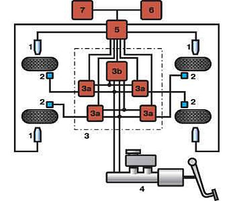
- 1 - wheel speed sensor;
- 2 - wheel brake mechanism;
- 3 - hydraulic block;
- 3a - solenoid valve;
- 3b - pump;
- 4 - master brake cylinder;
- 5 - control unit;
- 6 - control lamp in the instrument cluster;
- 7 - ABS switch
The ABS consists of four wheel speed sensors, a pressure distributor, an electronic control unit, four toothed rims mounted on the wheel hubs, as well as a control lamp and an ABS switch located on the instrument panel. The electronic control unit is installed under the rear seat cushion. The unit receives data on the wheel speed from the sensors and, based on this data, sends signals to the electromagnetic valves of the pressure distributor. The pressure distributor is installed in the engine compartment after the main brake cylinder. Four electromagnetic valves are installed on the distributor, from which tubes go to the working cylinders of the wheel brake mechanisms. According to the signal from the control unit, the valves maintain the required pressure in the hydraulic drive of each brake mechanism.
Warning: When performing electric welding work, it is necessary to disconnect the block with wires from the electronic control unit with the ignition off. When painting the body with subsequent drying in a chamber at a temperature of 85°C and above, the electronic control unit must be removed from the car. Otherwise, the control unit may fail.
Removal and installation the pressure distributor
Pressure distributor
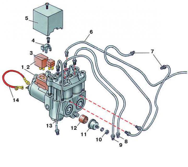
- 1 - pressure distributor;
- 2 - electromagnetic valve relay;
- 3 - pump relay;
- 4 - wire holder;
- 5 - lid;
- 6 - pipe to the brake mechanism of the front right wheel;
- 7 - tube to the brake master cylinder;
- 8 - pipe to the brake mechanism of the rear left wheel;
- 9 - pipe to the brake mechanism of the rear right wheel;
- 10 - nut;
- 11 - clip;
- 12 - rubber cushion;
- 13 - pipe to the brake mechanism of the front left wheel;
- 14 - wire to "ground"
1. Disconnect the wire from the negative terminal of the battery.
2. Pump out the brake fluid from the reservoir.
3. Disconnect the tubes from the pressure distributor.
4. Remove the cover by unscrewing the fastening screw.
5. Disconnect the wiring harness from the distributor.
6. Unscrew the fastening nut and disconnect the wire going to ground from the distributor.
7. Loosen the mounting nuts and remove the pressure distributor from the bracket.
8. Install the pressure distributor in the reverse order. When installing, replace the mounting nuts and tighten them to a torque of 7 N·m (0.7 kgf·m). After installation, bleed the brake hydraulic system.
Removal and installation of the electronic ABS control unit
1. Disconnect the wire from the negative terminal of the battery.
2. Remove the rear seat cushion.
3. Disconnect the wiring harness from the electronic control unit by squeezing the spring clamp.
4. Unscrew the two mounting nuts and remove the electronic control unit.
5. Install the electronic control unit in reverse order. The connector with wires can be connected to the control unit only with the ignition off or the battery disconnected.
Removal and installation the wheel speed sensor
Installing the front (a) and rear (b) wheel speed sensor
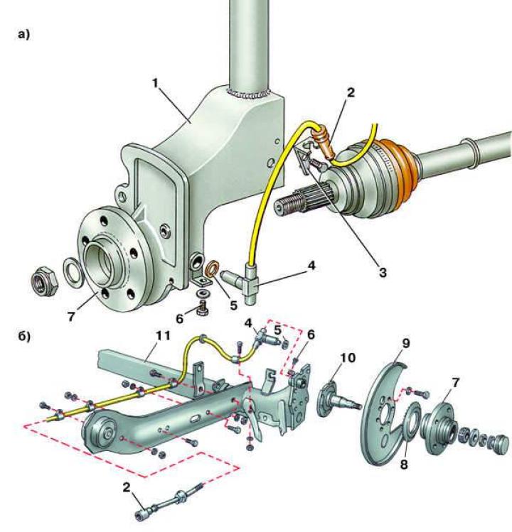
- 1 - steering knuckle;
- 2 - block with wires;
- 3 - holder;
- 4 - rotation speed sensor;
- 5 - gasket;
- 6 - bolt;
- 7 - hub;
- 8 - toothed crown;
- 9 - brake shield;
- 10 - trunnion;
- 11 - rear axle beam
1. Remove the wheel.
2. When removing the right front wheel sensor, you need to remove the windshield washer reservoir to disconnect the sensor block from the wiring harness, and the rear wheel sensors - the back of the rear seat. Disconnect the block.
3. Loosen the mounting bolt and remove the sensor.
4. Install the wheel speed sensor in reverse order.
(The text is based on materials from the website «AudiManual.ru»)