Repair Chevrolet Repair Toyota Repair Honda Repair AvtoVAZ Repair Mercedes-Benz Repair BMW Repair Opel
Home  |  Contacts  |  Sitemap  |    
English Русский
Български
Беларускі
Український
Српски
Hrvatski
Română
Polski
Slovenský
Magyar
AudiManual.ru


  • AUDI 80
  • AUDI 100
  • AUDI A3
  • AUDI A4
  • AUDI A6
  • AUDI A8
  • AUDI Q
  • OTHER
  • ARTICLES
B8 (2007-2015) B7 (2004-2008) B6 (2000-2006) B6 (2000-2006, petrol) B5 (1994-2001) B5 (1994-2001, petrol)

Anti-lock braking system in detail (Audi A4 B6)

  • Home
  • Audi A4
  • B6 (2000-2006, petrol)
  • Chassis
  • Brake system
  • Anti-lock braking system in detail
            0
Anti-lock braking system and vehicle stability control system parts: 1 - bracket for mounting…

Anti-lock braking system and vehicle stability control system parts: 1 - bracket for mounting hydraulic units, 2 - vacuum pump for brake booster (only for petrol engines with automatic transmission), 3 - control unit for anti-lock braking system with electronic differential lock (J104), 4 - hydraulic 6noK (N55), 5 - pressure sensor in the brake drive system, 6 - hydraulic control unit (J104 and N55), 7 - speed sensor rotor (front right), 8 - Front right speed sensor (G45), 9 - Low brake fluid level indicator contact (F34), 10 - Combined instrument panel, 11 - Push button for regulating the traction of the drive wheels (E132), 12 - Steering angle sensor (G85) if the vehicle stability control system is present, 13 - Lateral acceleration sensor (G200) and yaw rate sensor (G202), 14 - Parking brake system indicator switch (F9), 15 - Speed sensor rotor (rear right), 16 - rear right speed sensor (G44), 17 - rear left speed sensor (G46), 18 - speed sensor rotor (rear left), 19 - Anti-skid system and vehicle stability control system indicator (K86), 20 - Anti-lock braking system indicator (K47), 21 - "Brake system malfunction" indicator lamp (K118), 22 - Brake light switch (F), 23 - Speed sensor rotor (front left), 24 - front left speed sensor (G47).


Anti-lock braking system control device. This device is located in the engine compartment on the left. It continuously processes the speed data from the wheel sensors and compares it with the programmed values. If the wheels start to rotate at different speeds, which indicates the danger of one or more wheels locking, the control unit activates the hydraulic unit and the pressure for the corresponding wheel is reduced until it starts to rotate freely again, after which the braking process can be resumed. Depending on the road conditions, these changes can occur during the braking process at intervals of several milliseconds.

The control unit is also responsible for a number of systems to improve the vehicle's safety while driving. These systems include the electronic brake force distribution system, the electronic differential lock, and the electronic vehicle stability control system.

Electronic brakeforce distribution (EBV). A special program in the anti-lock braking system control unit regulates the brake pressure in such a way as to protect the rear wheels from excessive braking force. There is no need for a brake force regulator or pressure reduction valve.

Electronic Differential Lock (EDS). This device is used when starting off. When accelerating on a slippery road, it automatically brakes the slipping wheel. In this case, the drive torque is transmitted through the differential to the wheel that is not rotating. In front-wheel drive models, the differential locking device regulates up to a speed of 40 km / h, in all-wheel drive models - up to 80 km / h. This device is supplemented by an anti-slip system. The anti-slip system does not interfere with braking regulation, but with engine control. If the speed sensors, which are part of the anti-lock system, receive data on wheel slippage, then the engine power is reduced. This regulation is carried out at any speed.


Electronic stability program (ESP). This system automatically reduces the risk of skidding and thus increases the safety of the vehicle in critical situations. The system is able to brake individual wheels, which helps to stabilize the vehicle if it tends to skid. If, for example, the rear of the vehicle starts to skid, the anti-lock braking system brakes the front wheel that is located on the outside of the turn. The electronic stability control system, which is available at an additional cost, requires an additional hydraulic pump, which, if necessary, creates the appropriate pressure in the brake drive (see also the technical dictionary in the chapter "Chassis").

Hydraulic block. The main part of the anti-lock braking system. This unit is screwed to the control unit, and can only be separated when dismantled. The unit includes an electric pump and a valve block with electromagnetic valves. If the anti-lock braking system starts to operate, the control unit gives a command to reduce the pressure in the brake drive. The brake fluid flows from the valve block directly into the expansion tank. If the pressure in the brake drive increases again, the brake fluid from the tank is fed directly to the corresponding brake circuit via the hydraulic pump. The pump's operation can be seen by the brake pedal - the pedal begins to pulsate slightly.

The hydraulic unit and control device form a single unit. Direct connection eliminates sources of…

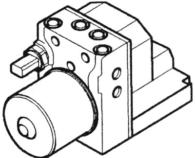
The hydraulic unit and control device form a single unit. Direct connection eliminates sources of malfunction. The screws that connect the individual parts of the hydraulic control unit must not be loosened. The unit is not repaired, but replaced


Rotation speed sensor. The sensor is mounted on each wheel at a small distance from the toothed disk (rotor), which is rigidly connected to the wheel hub. The rotor, together with its toothed projections, rotates past the sensor faster or slower depending on the wheel rotation speed. Each tooth of the pulse sensor induces a voltage pulse. Due to this, an alternating voltage is produced in the sensor, the frequency of which changes in accordance with the wheel rotation speed. Thus, the sensors measure the rotation speed of a particular wheel and transmit it as an electrical signal to the control device.

Anti-lock braking system malfunctions. The anti-lock braking system indicator lights up when the ignition is turned on and goes out when the engine is running. This happens no later than 2 seconds later, and also if the speed has exceeded 6 km/h. If the indicator lights up while driving, it means that either one of the wheels has been slipping for more than 20 seconds, or there is a malfunction in the anti-lock braking system. Another reason could be a voltage drop below 10 volts. Despite the indicator lighting up, you can continue driving, but the braking system functions as if the car does not have an anti-lock braking system. In this case, you should be careful, since the electronic brake force distribution does not work, and the rear wheels may lock.

To eliminate this defect, you should contact the workshop. The workshop will use a special device to interrogate the system fault codes stored in the memory of the control device.
The article was checked by auto expert Alexey Ivanov
This article is available at russian, bulgarian, belarusian, ukrainian, serbian, croatian, romanian, polish, slovak, hungarian

Share information:
Previous articles
Audi A4 B6: Brake system
Next articles

Brake system — design description
Brake maintenance: If in doubt, consult a workshop
Checking the brake fluid level
Checking the condition of the brake system
Checking the brake booster


Similar articles on other Audi car models:
Anti-lock braking system (ABS) — general description Audi 80 B3 (1986-1991, petrol)
Anti-lock braking system indicator Audi 100 C4 (1990-1994, petrol)
Anti-lock Brake System ABS and Control Unit Connector Audi A3 Type 8L (1996-2003)
General description of the anti-lock braking system (ABS) Audi A6 C4 (1994-1997)
Anti-lock braking system (ABS) Audi A8 D2 (1994-2002)
Keys, remote control, single lock, Advanced Key system Audi Q7 Typ 4L (2005-2015, diesel)
Radio or Navigation System Plus — Activating Security Coding Audi A2 (1999-2005)
Link to this page in different formats


Visitor comments

No comments yet


How much will 30 + 28 =


A4(B8, 2007-2015) 
  • General information
  • Operating instructions
  • Power unit
  • Petrol engines 1.8 l
  • Petrol engines 1.8/2.0 l
  • Petrol engines 3.0 l
  • Petrol engines 3.2 l
  • Fuel system (petrol)
  • Diesel engines 2.0 l (CA*)
  • Diesel engines 2.0 l (CJCB)
  • Diesel engines 2.7/3.0 l
  • Diesel engines 3.0 l
  • Fuel system (diesel)
  • Transmission
  • Manual gearbox 0B1
  • Manual gearbox 0B2
  • Manual gearbox 0B3
  • Manual gearbox 0B4
  • Automatic transmission 0B5
  • Automatic transmission 0B6
  • Automatic transmission 0AW
  • All-wheel drive system
  • Chassis
  • Front suspension
  • Rear suspension
  • Brake system
  • Steering system
  • Body
  • Exterior
  • Interior
  • Seats
  • Doors, locks and windows
  • Security system
  • Heating and air conditioning
  • Electrical equipment
  • Audio system
  • Power devices
  • Equipment and devices
  • Lighting and lamps
  • Electrical circuits
 
A4(B7, 2004-2008) 
  • General information
  • Introduction to manual
  • Troubleshooting
  • Operating instructions
  • Maintenance
  • Power unit
  • Petrol engines 2.0 (ALT)
  • Petrol engines 2.0 (TFSI)
  • Petrol engines 1.8 (MPI)
  • Diesel engines
  • Cooling system
  • Air conditioner
  • Fuel and exhaust system
  • Ignition system
  • Starting and charging
  • Transmission
  • Clutch
  • Manual gearbox
  • Automatic gearbox
  • Drive shafts
  • Chassis
  • Brake system
  • Front suspension
  • Rear suspension
  • Steering
  • Body
  • Exterior
  • Interior
  • Electrical equipment
  • Equipment and devices
  • Lighting and signaling
  • Windscreen wipers and washers
  • Electrical diagrams
  • Electrical diagrams (since 2007)
 
A4(B6, 2000-2006) 
  • General information
  • Vehicle Description
  • User manual
  • Maintenance
  • Power unit
  • Gasoline engine
  • Diesel engine
  • Lubrication system
  • Cooling system
  • Supply system
  • Injection system
  • Exhaust system
  • Ignition and control
  • Transmission
  • Gear box
  • Clutch and drive shafts
  • Chassis
  • Brake system
  • Car suspension
  • Steering
  • Body
  • Heating and ventilation
  • Exterior (external elements)
  • Interior (internal elements)
  • Electrical equipment
  • Power devices
  • Lighting and appliances
  • Electrical circuits
 
A4(B6, 2000-2006, petrol) 
  • General information
  • Introduction to the guide
  • Car care
  • Power unit
  • Engine repair
  • Lubrication system
  • Cooling system
  • Injection and control system
  • Ignition system
  • Power and exhaust system
  • Transmission
  • Clutch and drive shafts
  • Car gearbox
  • Chassis
  • Suspension and wheels
  • Steering
  • Brake system
  • Body
  • Interior
  • Exterior
  • Electrical equipment
  • Equipment and devices
  • Lighting and signaling
  • Power devices
  • Electrical circuits
 
A4(B5, 1994-2001) 
  • General information
  • Introduction to the guide
  • Car care
  • Maintenance (gasoline)
  • Maintenance (diesel)
  • Power unit
  • Gasoline engines
  • Diesel engines
  • Engine overhaul
  • Cooling system
  • Fuel injection (gasoline)
  • Fuel system (diesel)
  • Exhaust system
  • Ignition system
  • Transmission
  • Clutch
  • Mechanical gearbox
  • Automatic gearbox
  • Drive shafts
  • Chassis
  • Brake system
  • Car suspension
  • Steering
  • Body
  • Exterior
  • Interior
  • Doors, locks and windows
  • Heating and ventilation
  • Electrical equipment
  • Power devices
  • Equipment and devices
  • Electrical circuits
 
A4(B5, 1994-2001, petrol) 
  • General information
  • Vehicle description
  • Maintenance
  • Power unit
  • Engine repair
  • Turbocharging
  • Exhaust system
  • Cooling system
  • Ignition system
  • Fuel system
  • Motronic injection system
  • MPI and MPFI injection system
  • Transmission
  • Clutch
  • Gearbox and shafts
  • Chassis
  • Steering
  • Car suspension
  • Brake system
  • Wheels and tires
  • Body
  • Heating and ventilation
  • Body parts
  • Electrical equipment
  • Fuses and relays
  • Power devices
  • Lighting and lamps
  • Tools and devices
  • Electrical circuits
 
AudiManual.ru © 2017-2026 · Mobile version · Feedback · Sitemap: EN BG BY UA RS HR RO PL SK HU · Site search · News and articles
80 B2 · 80 B3 petrol · 80 B3 · 80 B4 · 100 C3 diesel · 100 C3 petrol · 100 C3 · 100 C4 petrol · 100 C4 · A3 Type 8L · A4 B5 petrol · A4 B5 · A4 B6 petrol · A4 B6 · A4 B7 · A4 B8 · A6 C4 · A6 C5 · A6 C5 Allroad · A8 D2 · Q5 Type 8R · Q7 Typ 4L · Audi A2 ·
This site uses cookies 🍪. Click the button to accept this fact.