
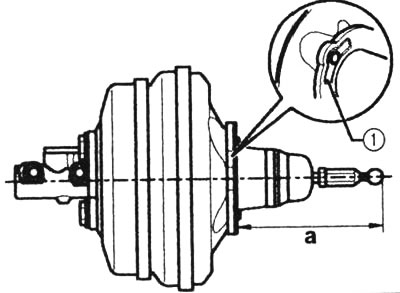
A prerequisite for the functioning of the brake booster is the correct adjustment of the ball head: 1 — support surface for installation dimension a=159±0.5 mm. When measuring, the ball head should be directed at a right angle to the surface of the brake booster. The measurement should be made without sealing to the end of the head. Tightening torque of the ball head of the brake booster: 30 Nm.
1. Turn off the engine, depress the brake pedal several times and hold it in the lowest position.
2. Start the engine. After this, the pedal should move down a little, if the pedal does not move down, then in most cases this is caused by the following reasons:
- Leakage in vacuum hose 1 between intake manifold and brake booster. In this case, replace the hose.
- The rubber ring 14 between the main brake cylinder and the brake booster is worn out. To replace the ring, it is necessary to dismantle the cylinder.
- The booster membrane is defective. The membrane cannot be repaired. Replace the entire brake booster assembly at a workshop.
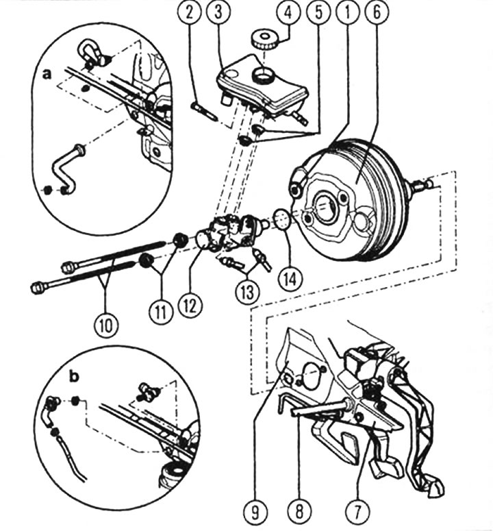
Dual brake booster and master cylinder (installation diagram): 1a - vacuum hose(1.6 l, 2.0 l - manual transmission), 1b - vacuum hose (1.6 l, 2.0 l, 3.0 l - automatic transmission, 3.0 l - manual transmission), 2 - screw with cylindrical end 10 Nm, 3 - brake fluid reservoir with float switch, 4 - cover, 5 - ground plug, 6 - brake booster, 7 - pedal bracket, 8 - hose, 9 - front wall, 10 - bolt 25 Nm, 11 - flange nut 50 Nm, 12 - brake master cylinder (in case of malfunction, replace as a set), 13 - brake line 15 Nm, 14 - sealing ring (after removing the master brake cylinder, replace it).