
When bleeding air, you will need fresh brake fluid (specification according to the American standard FMVSS 116 DOT 4) and a transparent hose. In addition, you will need the help of a second person. The car must be on level ground on all four wheels. Attention! During the removal of air, constantly monitor the level of brake fluid in the reservoir! If necessary, add the appropriate amount of fluid to the reservoir. The reservoir must not be empty, otherwise air will get into the system again.
Safety note: If the fluid level in the reservoir drops so low during bleeding that air is sucked in, the air must be bled from the system in a workshop using a special device, as air can get into the hydraulic pump of the anti-lock system. After installing a new brake hose, the air must also be bled in a workshop.
1. If necessary, treat all air valves with rust remover a few hours before bleeding. This reduces the risk of the valves being torn off when loosening.
2. Sequence of operations for removing air: rear right wheel brake cylinder - rear left wheel brake cylinder - front right wheel brake cylinder - front left wheel brake cylinder.
3. Remove the rubber cap from the air valve and clean the valve.
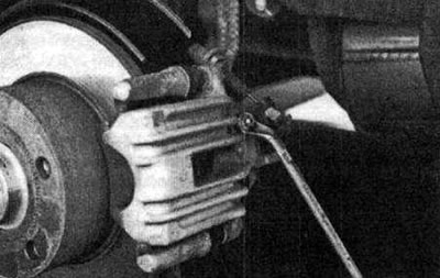
The air valve is best loosened with a ring spanner
4. Slide a plastic hose onto the valve and lower the other end of the hose into a container to collect the leaking fluid. The container should be partially filled with brake fluid.
Bleeding the brake system: A transparent hose is attached to the valve. The toxic, varnish-corrosive brake fluid drains into a container.
5. Use a ring spanner to loosen the valve no more than one turn. At this time, the assistant should slowly press the brake pedal to the floor to pump out the brake fluid and the air contained in it. At the same time, watch the hose and the reservoir - you should see air bubbles. The assistant should hold the pedal to the floor.
6. Close the air valve. Only then can you release the pedal.
7. Repeat this process until no more air bubbles appear. Constantly monitor the fluid level in the reservoir, if necessary, add fluid, but only so much that the initial level is not exceeded. This will prevent a situation where, when the brake pads are replaced later, there is too much brake fluid in the system and the reservoir overflows when the brake cylinder pistons are pressed back. Before performing the next bleeding, wait about three seconds for the master brake cylinder to fill with brake fluid again.
8. After the final pumping, the assistant should hold the pedal to the floor until the air valve is completely closed (do not hit the valve!).
9. Repeat all described operations on other air valves.
10. If the air cannot be completely removed using the method described, close all air valves, start the engine and apply the brake several times. Then repeat the air removal process.
11. Finally, check all brake lines again (are they tightened?), fluid level in the reservoir and brake operation during a test drive. Brake once so that the anti-lock regulation works.