
1. First remove the storage box on the driver's side.
2. The brake light switch 1 will now be visible. To remove the switch, turn it 45° to the left (arrow).
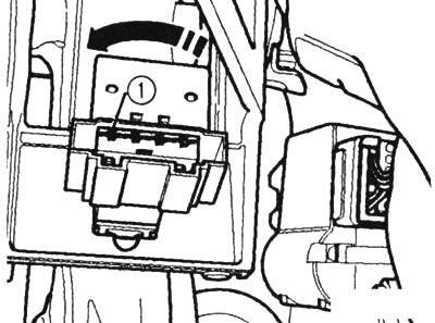
After removing the storage box on the driver's side, the brake light switch 1 becomes visible
3. Using tool T40024, separate the brake pedal from the brake booster.

Separating the brake pedal from the brake booster
4. Remove the battery compartment cover and protect the engine compartment from leaking brake fluid. Open the brake fluid reservoir (arrow) and insert the air bleeder hose into it.
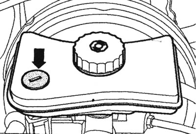
Bleed plug on brake fluid reservoir
5. Remove the connector from the float switch sensor 1. Also remove the vacuum hose 2.
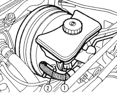
Remove the connector from the float switch sensor 1 and the vacuum hose 2
6. Remove the T-bolt securing the brake fluid reservoir. The reservoir is engaged with the master cylinder at the bottom. To remove the reservoir, press the locking tab downwards and simultaneously pull the reservoir out of the ground-in plugs. Remove the reservoir and set it aside.
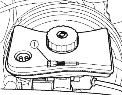
Unscrew the brake fluid reservoir
7. Unscrew brake pipes 1 and 2 from the master brake cylinder and close them with plugs,
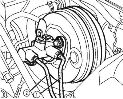
Unscrewing brake pipes 7 and 2 from the master brake cylinder
8. Before unscrewing brake pipes 1 and 2 from the control device and removing them together with the rubber bushing, lay out a non-soaked rag in the area of the hydraulic unit.
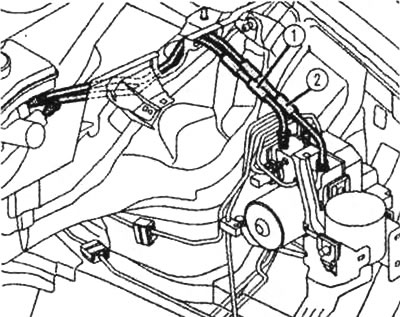
Before unscrewing the brake pipes, cover the hydraulic unit with a non-soaked rag
9. To remove the brake booster together with the brake master cylinder, unscrew the booster mounting screw (with star slot). In addition, to remove the master brake cylinder from the booster, unscrew the cylinder mounting nuts 1.
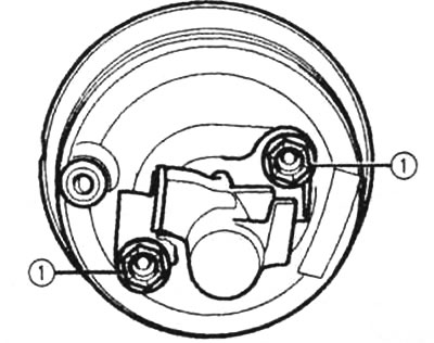
Brake master cylinder retaining nuts 1
10. When installing in the reverse order, make sure that the accumulator section is clear of any leaked brake fluid. When assembling the master cylinder and brake booster, make sure that the push rod is seated correctly in the cylinder. To facilitate insertion of the rod, lightly press the brake pedal and move it toward the cylinder.
11. Install the brake light switch.
12. Remove air from the brake system.
The original text is available on the website AudiManual