
Table of contents: Checking cylinder diameters ↓ Checking the clearances between the… ↓ Checking the axial clearance of the… ↓ Checking the dimensions of pistons… ↓ Engine assembly ↓
Checking cylinder diameters
Make precise measurements of the cylinder diameters. Use a bore gauge in three zones, both in the transverse direction "A" and in the longitudinal direction "B", as shown in the diagram.
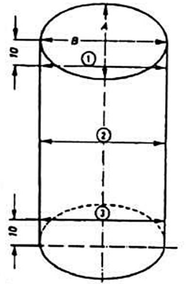
Cylinder diameter welding diagram:
A and B are the directions of measurements
1, 2, 3 — measurement belts
In cases where wear exceeds the permissible value by more than 0.08 mm, repair the cylinders to the nearest repair size and install pistons of the corresponding repair size.
Checking the clearances between the bearings and the crankshaft journals
Thoroughly clean the working surfaces of the bearings and the corresponding crankshaft journal. Place a piece of plastic calibrated wire equal in width to the bearing on the journal surface.
Depending on the type of journal being checked, install the connecting rod with the cap or the main bearing cap on the journal and tighten the nuts or mounting bolts accordingly. First tighten the connecting rod bolt nuts to a torque of 3.0 kgf·m, and then tighten them 180°. Tighten the main bearing cap bolts to a torque of 6.5 kgf·m. Do not allow the engine crankshaft to turn.
Carefully remove the lid and determine the gap size using the school marked on the package, the scale marked on the package, and the flattening of the wire. More detailed information is provided in the accompanying documentation from the manufacturer of the calibrated wire.
The nominal design gap is 0.030-0.080 mm (maximum permissible 0.17 mm) for root and 0.015-0.062 mm (maximum permissible 0.12 mm) for connecting rod journals.
If the clearance is greater than the maximum, replace the bearings or grind the crankshaft journals.
Checking the axial clearance of the crankshaft
Check the axial clearance of the crankshaft using a feeler gauge on the middle support, which should be no more than 0.25 mm.
If necessary, achieve the proper clearance by installing thicker thrust washers.
Checking the dimensions of pistons and piston rings
Determine the degree of piston wear by measuring the diameter 10 mm from the edge of the piston skirt perpendicular to the axis of the piston pin. The piston must be replaced if its diameter differs by more than 0.04 mm from the permissible values (see subsection "Detailed technical specifications").
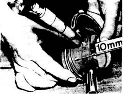
Place of measurement of the piston outer diameter
Replace piston rings or pistons if the clearances between piston rings and grooves exceed the permissible values (see subsection "Detailed technical specifications").
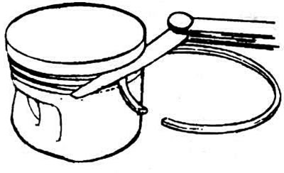
Checking the clearance between the piston rings and the grooves
Engine assembly
The liners of the 1st, 2nd and 5th main bearings do not have lubrication grooves. The liners of the 3rd bearing supplied as spare parts have flanges. On the thrust half rings from the axial displacement of the crankshaft from the cylinder block side there is a projection directed towards the liners.
Install three piston rings into the corresponding grooves in the pistons, arranging their locks at 120° intervals.
Orient the piston ring locks forward or backward as the vehicle moves. The lower compression and oil release rings are marked "top" or "oben" ("top"), which should be turned up when installing the ring in the groove.
Install the pistons by orienting the arrow stamped on the piston bottom forward in the direction of vehicle travel (towards the camshaft drive).
Lubricate the pistons and piston rings with engine oil, compress the piston rings in the grooves with the appropriate mounting sleeve and insert the pistons with connecting rods into the cylinders.
Install the bearings into the connecting rods and connecting rod caps in accordance with the marks made during disassembly if worn bearings are used.
Install the connecting rods and caps onto the crankshaft journals, with the ridges on the caps and the locking protrusions on the liners facing towards the intermediate shaft.
Lightly tighten the connecting rod bolt nuts, then tighten them to the final torque specification.
Install the rear seal retainer with a new cardboard gasket. Press the seal into the retainer using mandrel 2003/1.
Install the flywheel, ensuring that the surface under the driven clutch disc protrudes relative to the cylinder block within 30.50-32.10 mm.
If necessary, install a spacer washer between the flywheel and the crankshaft flange. Install a lock washer on the flywheel with the beveled edge facing the flywheel. Apply a layer of adhesive to the mounting bolts beforehand.
Install the front crankshaft oil seal retainer with a new cardboard gasket. Press the new oil seal into the retainer using tool 3083.
Insert the intermediate shaft into the cylinder block. Install the holder with the pressed-in oil seal and the sealing gasket onto the intermediate shaft.
Install the oil pump, having first checked its technical condition (see below).
Install the oil pan with a new gasket.
Install the cylinder head.
Install the camshaft drive belt.
Install the coolant pump.
(Text provided by the online resource «AudiManual.ru»)