
Table of contents: Replacing the inner CV joint ↓ Replacing the outer CV joint ↓
Replacing the inner CV joint
In the assembly diagrams of both drive shaft variants of Audi models, the drive shaft for the installed automatic transmission comes with the CV joint and is not subject to repair. In the subsequent description, it should be borne in mind that only the inner joint cuff can be replaced for this shaft.
The following operations must be carried out using the drawings as a guide. The inner CV joint cannot be repaired and must be replaced if damaged. Before replacing, read the section at the beginning of the chapter regarding the use of joints of different sizes. The joint must also be removed if the protective cuff needs to be replaced.
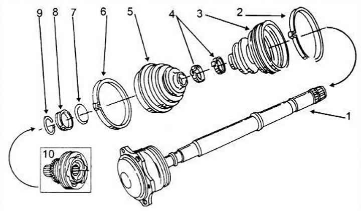
Drive shaft parts on models with automatic transmission
1 Shaft with joint
2 Fastening clamp
3 Cuff
4 Clamp clamp
5 Cuff
6 Fastening clamp
7 Washer
8 Distance washer
9 Retaining ring (is replaced)
1Outer CV joint
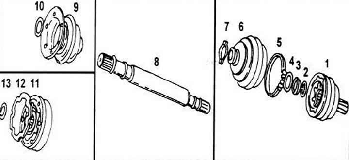
Drive shaft parts for models with manual transmission
1 Outer CV joint
2 Fastening ring (is replaced)
3 Distance washer
4 Washer
5 Clamp
6 Cuff
7 Clamp clamp
8 Drive shaft
9 Cuff and cap
10 Washer
11 Inner CV joint
12 Gasket
13 Fastening ring (is replaced)
Clamp the drive shaft in a vice.
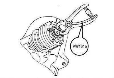
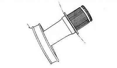
Using similar pliers (VW 161a), remove the retaining ring from the end of the inner CV joint. The retaining ring should always be replaced.
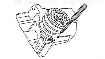
Using a punch, carefully knock the protective cap off the hinge. Place the punch in several places around the circumference to avoid deforming the cap.
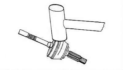
Place the shaft under the press and press the shaft through the hinge. The hinge should be located as close to the middle as possible.
Pull the spring washer off the shaft (not available on all shafts). In this case, pay attention to the installation method, since the washer is curved (installation see below).
Clean the drive shaft thoroughly before installing the new joint.
Spring washer (if any) install on the shaft so that the bulge points towards the shaft with a curved line.
Press the CV joint onto the shaft, supporting the shaft from below. The bevel on the inner diameter of the center of the ball should be directed toward the thrust flange of the shaft. Support the shaft well from below and press the joint until it stops.
Insert a new retaining ring into the groove. If necessary, press it in using a special clamp.
Fill the joint with G6 grease. For a joint diameter of 100 mm, 180 g of grease is required - 50 g in the cuff (cover) and 30 g in the joint. For a joint diameter of 108 mm, 30 g of grease is required in the joint and 85 g in the cuff. The grease must be tightly packed so that the joint can work properly. Mix the grease well in the joint.
Carefully hammer the protective cap back onto the hinge.
Put the cuff on the drive shaft. In the workshop, special pliers are used to tighten the clamp. If you don't have them, you need to be careful when tightening the cuff so that the clamp doesn't slip off. Before the cuff is closed, you need to squeeze it a little so that the air that got in there comes out. If, after assembly, you find retracted places, then loosen the cuff on the smaller diameter and carefully pry it up with a screwdriver to let in air and equalize the existing vacuum. In this case, of course, you should pay attention not to damage the cuff with a screwdriver.
Clean the shaft and seals thoroughly, as road dust and dirt quickly stick to the grease.
Note: The inner joint of the shaft for the automatic transmission is filled with 14g of grease G 00605. Only when replacing the cuff should the joint be lubricated again. Evenly distribute the grease between the joint and the cuff.
Replacing the outer CV joint
Both the inner and outer CV joints can only be replaced completely. As stated above, the outer joint varies between models with different engines. The beginning of the chapter indicates what to pay attention to and which joint you will have to deal with.
Removal the CV joint
Remove the clamps at both ends of the rubber cuff and pull the cuff along the shaft along the CV joint.
Clean the inside of the hinge.
Clamp the shaft in a vice with soft metal jaws (tin, aluminum) and knock the joint off the shaft with an aluminum or copper hammer so that it can be removed from the shaft, and the mounting spring inside jumps out of the groove. For an automatic transmission shaft, the parts must be marked in their original positions before removal.
Installing CV joints
Place the rubber cuff on the shaft and slide it along it.
Distribute the used lubricant precisely. With a joint diameter of 89 mm, 40 g of the above lubricant goes into the joint and 50 g into the cuff. In the case of a CV joint of a different diameter, 80 g goes into the joint and 40 g into the cuff.
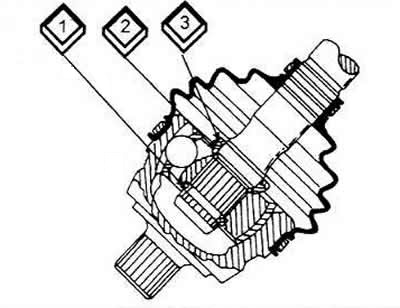
1 Retaining ring
2 Distance washer
3 Spring washer
Slide the spring washer with internal teeth onto the shaft so that the bulge is at the hinge and the adjusting washer protrudes.
Place a new snap ring on the shaft, clamp the shaft in a vice and hammer the joint onto the shaft with a brass or aluminum hammer until the snap ring fits into the groove on the inside of the joint.
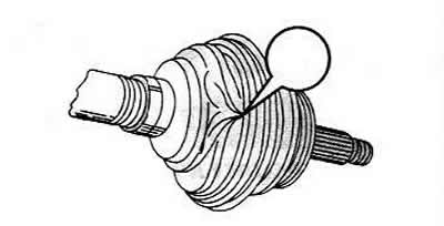
Pull the rubber cuff onto the CV joint and secure it with clamps. Before tightening the cuff, it should be slightly compressed to squeeze out any air that has gotten in there. If there are any retracted areas after assembly, then loosen the cuff back on the smaller diameter and carefully pry it up with a screwdriver so that air gets in and the existing vacuum can be compensated. When prying the cuff up with a screwdriver, be careful not to damage the cuff.
(Material republished from the website: audimanual.ru)