
Table of contents: Removal and installation the master… ↓ Removal and installation of the… ↓
The clutch is driven hydraulically using the master and slave cylinders. The master cylinder is located on the pedal block, secured with two bolts and held on the clutch pedal by a bolt with a cotter pin.
The working cylinder is located on the top of the gearbox (gearbox) and is bolted. The installation method for both cylinders is shown in the figure below.
The master and slave cylinders of the clutch cannot be repaired. Loss of pressure due to wear or damage to parts means that new units must be installed.
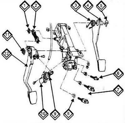
Installing the pedals and clutch master cylinder
1 Lock washer
2 Servo spring
3 Spring
4 Brake pedal
5 Lock washer
6 Brake light switch
7 Air bleed valve
8 Stoppers
9 Lock nut
10 Clutch master cylinder
11 Lock washer
12 Clutch pedal
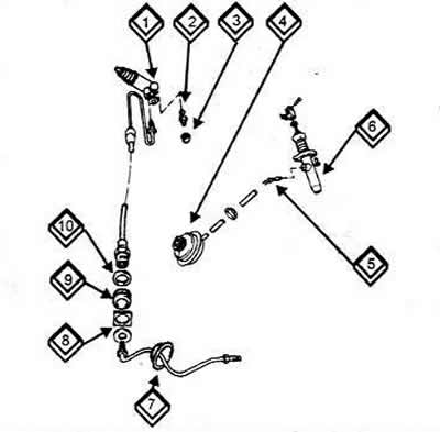
Clutch between master and slave cylinder
1 Clutch slave cylinder
2 Air bleed valve
3 Dust cover
4 Brake fluid reservoir
5 Curved nipple
6 Clutch master cylinder
7 Rubber seal
8 Holder
9 Bushing
10 Ring
Removal and installation the master cylinder
Removal is done mainly from the inside (from the passenger compartment) of the car. You need to prepare to remove the trim from the left side.
Unscrew the brake fluid reservoir cap and suck out as much fluid as possible using a syringe or rubber bulb. Make sure that the brake fluid does not get on painted surfaces and never suck out the fluid with your mouth through a hose - it is poisonous! Now you can remove the trim as follows:
Remove the fuse box cover from outside the instrument panel (2 bolts underneath it at the bottom).
Remove the 4 trim mounting screws. These are the two already mentioned bolts in the fuse box and two others (arrows). They are located on the right and left of the steering wheel. Now move the trim down a little and pull it back.
Place thick rags on the cabin floor to collect any leaking fluid as the hose is now pulled off the master cylinder connection.
Unscrew the union nut of the working cylinder pipeline in the engine compartment. On this side, also unscrew the two nuts of the mounting bolts.
In the cabin, remove the clamp securing the master cylinder pusher pivot bolt from the clutch pedal and remove the bolt.
Carefully remove the master cylinder. Watch out for any brake fluid that may still drip out.
When installing a new cylinder, the push rod must be adjusted (fork head on the pushrod) so that the clutch pedal is approximately 10 mm higher than the brake pedal. Check whether the auxiliary spring returns the clutch pedal and that the pedal does not rest against the pedal block in its original position, since if this is not paid attention to, the consequence will be increased wear of the clutch.
After installation, bleed the hydraulic system as described below. If the clutch pedal does not return to its original position and the car has a high mileage, it may be that the pedal is stiff or the auxiliary spring is not working properly.
Removal and installation of the working cylinder
Raise and support the car from the front, as you will have to work in the front left.
Place a thick cloth around the cylinder on the gearbox and unscrew the union nut of the pipeline. Pull out the tube and immediately wipe off the leaked liquid.
Loosen the mounting bolt on the cylinder and pull the cylinder back from the gearbox. Sometimes it "sticks" and is difficult to move. In this case, you can use some anti-rust agent. If this does not help, you should use a crowbar.
Lightly lubricate the outside of the new cylinder. Apply a little graphite grease to the joint between the pushrod and the clutch release lever.
Push the cylinder into the gearbox so that the bolt can be inserted and tightened. Tightening torque is 25 Nm.
Finally, screw on the tube and bleed the hydraulic drive as described below.