
Table of contents: Checking injection nozzles ↓ Throttle potentiometer ↓ Air flow meter (mPI only) ↓ Idle speed stabilization valve (mPI… ↓ Intake air temperature sensor (mPFI… ↓ Checking the lambda probe ↓ Replacing the lambda probe ↓
Checking injection nozzles
If you suspect that one of the injectors is not working, it is easy to check with an LED voltmeter and an accurate ohmmeter.
Disconnect the plugs from all injection nozzles.
First check the voltage: LED voltmeter (not a control lamp) connect to the plug contacts. Start the engine: the LEDs in the voltmeter should flicker, otherwise there is no power supply or the control unit connecting the "ground" is faulty. This check cannot be carried out with a conventional measuring device.
Resistance check: disconnect the plugs of the injection nozzles, connect an ohmmeter to both contacts of the nozzle: on a cold engine it should show 13.5-17 Ohms.
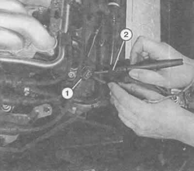
With the plug (1) removed, you can check the power supply to the injection nozzles using an LED voltmeter (2). When the engine is turned over using the starter, the LEDs in the voltmeter should flicker. Otherwise, there is no power supply.
If the reading is outside the specified limits, replace the injector (if the measurement was accurate).
Checking for leaks: remove the fuel distributor together with the injectors.
The injection nozzle plugs are removed, the fuel line hoses remain connected.
Have an assistant turn the engine over several times using the starter to activate the fuel pump and build up operating pressure.
Watch the injection nozzles: each individual nozzle should lose no more than 1-2 drops of fuel per minute. Otherwise, the leaky nozzle should be replaced.
Regardless of this, you can check the injection jet and injection quantity of the injector if this is necessary due to interruptions in engine operation.
Throttle potentiometer
Disconnect the throttle potentiometer plug.
Using an accurate ohmmeter, measure the resistance between the potentiometer contacts.
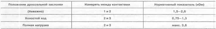
It is necessary to measure in the throttle valve positions "idle" and "full load" with the engine not running.
The ohmmeter should show the following standard values:
Air flow meter (mPI only)
Move the rubber tip of the air flow meter back, leave the plug connected.
Connect an accurate voltmeter from the back side to the plug contacts, according to the described diagram:
Measurement 1: Connect the connecting wire to contacts 2 and 3. Turn on the ignition.
The voltmeter should show 12-14 V. Otherwise, the power supply is faulty.
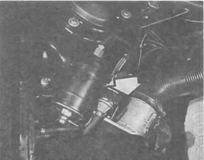
The 2.8-liter engine has an air flow meter (arrow) in the rear right engine compartment, connected by flanges to the air filter housing.
Check fuse #27, if necessary check the wire from fuse #27 to plug contact 3 of the air flow meter.
Or check the connection to the motor body (contact 2).
Measurement 2: Connect the connecting wire to pins 2 and 4.
Turn on the ignition.
The voltmeter should show 1.0-7.5 V. Otherwise, there is a defect in the CO-potentiometer in the air flow meter. Replace the air flow meter.
Measurement 3: Connect the connecting wire to pins 1 and 2.
Turn on the ignition.
The voltmeter should show 0.3-1.1 V.
Start the engine (the wire remains connected) Turn off all electrical consumers and make sure that the cooling system fan is not running.
Continuously vary the engine speed between idle and 4000 rpm.
The voltmeter should show (depending on the rotation frequency) between 1.5 and maximum 3.4 V. Otherwise, the air flow meter is faulty. Replace.
Idle speed stabilization valve (mPI only)
The 2.8-liter engine's speed stabilization valve is located on the right side of the throttle body. It is checked as follows:
Disconnect the idle speed control valve plug and connect an accurate ohmmeter to both valve plug contacts.
The device should show 7-11 Ohms, otherwise the valve is faulty.
Further check of operation: remove the idle speed control valve; the plug remains connected. The rotating piston in the air passage hole in the valve is set to the "open" or "closed" position (do not use metal tools!).
Turn on the ignition. The rotating piston should be approximately in the middle position.
Check the ease of movement of the rotating piston: it can be set in motion by briefly turning the removed valve.
In addition, there should be no signs of friction or grooves on the piston.
Idle speed stabilization valve (mPFI only)
Attention! The idle speed stabilization valve of the 2.6-liter engine cannot be dismantled using improvised means, because after reinstallation, the so-called basic adjustment of the injection system becomes necessary, and this can only be done using the VAG 1551 fault memory reader in an Audi workshop.
In addition: if the idle speed stabilization valve plug is disconnected before one and a half hours have passed since the last engine shutdown, the fault "idle speed stabilization valve faulty" is recorded in the fault memory (which may not be true at all). You can only check the winding on this valve:
Disconnect the idle speed control valve plug.
Measure the resistance between valve plug contacts 1 and 4, as well as 2 and 3, using an accurate ohmmeter.
If the valve is in good condition, the resistance should be 45-60 0m, otherwise the valve should be considered faulty.
Further testing using home remedies is not possible.
If the workshop replaces the valve, it also carries out the mentioned basic adjustment at the same time.

Different types of execution of the idle stabilization valve. On the left is a 2.6 - liter engine, on the right is a 2.8 - liter engine.
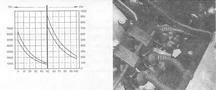
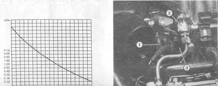
The coolant temperature sensor is located at the rear left of the engine (screwed into the cooling system hose) for the ignition/injection system (arrow). The diagram shows the resistance value of the sensor depending on the temperature.
Warning! If the coolant temperature sensor plug of the 2.6-liter engine model is disconnected within one and a half hours after the engine has stopped running, the following message will be written to the fault memory: "coolant temperature sensor faulty" (which may not be true at all).
General note: The temperature sensor may be the reason why the engine does not operate correctly in certain temperature ranges. Check:
Disconnect the coolant temperature sensor plug.
Using an accurate ohmmeter, measure the resistance between both sensor plug contacts.
Compare the obtained test result with the standard values in the diagram above depending on the coolant temperature. If the value deviates significantly from the standard, replace the temperature sensor.
As an addition, here are two more average resistance values: at 20°C coolant temperature, the resistance should be approximately 2.5 kOhm, at 80°C – approximately 330 Ohm.
Intake air temperature sensor (mPFI only)
Attention! If the plug of the intake air temperature sensor is disconnected before one and a half hours have passed since the engine stopped running, the following message is written to the memory: "intake air temperature sensor is faulty" (which may not be true at all).
Disconnect the intake air temperature sensor plug.
Using an accurate ohmmeter, measure the resistance between both sensor plug contacts.
Compare the obtained test result with the standard values in the diagram below depending on the intake air temperature. If the value deviates significantly from the standard, replace the temperature sensor.
As an addition, another average resistance value: at 20°C (room temperature, cold engine) the resistance should be approximately 6.3 kOhm.
Checking the lambda probe
To do this check, you need to disconnect the plug connection in the wiring to the lambda probe. The plug connections to the left and right probes are shown in the illustration on the next page.
The test is carried out using a precise ohmmeter:
Checking the special heating: Disconnect the plug to the lambda probe heating.
The standard value for a properly functioning heating system is 3-15 Ohm.
Otherwise, replace the lambda probe.
Checking the lambda probe: disconnect the plug to the lambda probe (calibrated wire).
Connect the ohmmeter to the plug contacts, to the probe to the engine body.
Standard value for a properly functioning probe: ∞ Ohm.
Otherwise, replace the lambda probe.
Checking the line to the control unit: disconnect the plug from the lambda probe (calibrated wire) (as we have already done).
Connect the voltmeter to the contacts of the plug to the control unit and to the engine body.
If the wiring is in good condition, the reading should be 0.35-0.45 V.
Otherwise, check the wiring.
If the wiring is OK, replace the control unit.
Replacing the lambda probe
Disconnect the wire ends and loosen the cable ties.
Before installing the probe, lubricate the thread with mounting paste. The paste should not get into the probe slot.
Tightening torque: 50 Nm.