
Table of contents: Additional signals ↓ Control unit ↓ Injection nozzles ↓ Fuel distributor ↓ Fuel supply control regulator ↓ Fuel pump and relay ↓ Air flow meter (mPI only) ↓ Pressure sensor (mPFI only) ↓ Temperature sensor (mPFI only) ↓ Throttle body ↓ Throttle potentiometer ↓ Idle speed stabilization valve ↓
To better understand the overall functioning of this injection system, it is necessary to first become familiar with the individual tasks of the component parts.
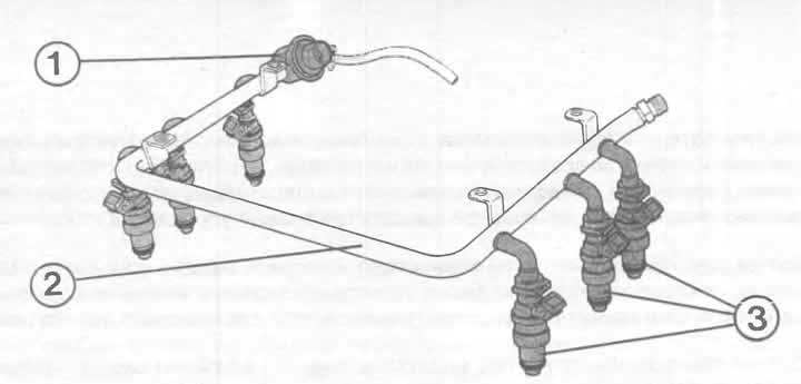
The illustration shows the MPI/MPFI injection system. The numbers indicate:
1 — fuel supply pressure regulator;
2 - fuel distributor;
3 - injection nozzle.
Additional signals
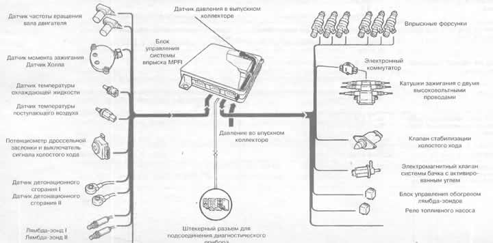
This diagram shows the ignition and injection system in detail, using the example of an MPFI system with a pressure sensor in the exhaust manifold. On the left side are the sensors and gauges that influence the behavior of the control unit. On the right are the components of the ignition and injection systems to which the control unit sends its commands.
Control unit
Between the incoming (from various sensors) information and the injection nozzles is located in the control unit. It enables the engine to receive a precisely defined amount of fuel, depending on the current load and temperature conditions. To achieve this, the control unit varies the duration of the opening of the electromagnetically driven injectors. Since the pressure in the fuel supply system remains practically constant, the amount of fuel injected can only be regulated by changing the injection duration. Where does the control unit get the information according to which it sets this injection duration? Various sensors are responsible for this:
2.8-liter MPI engine only: air flow meter; it provides information about the amount of air received.
2.6L MPFI engine only: Exhaust manifold temperature sensor; it communicates in conjunction with the exhaust manifold pressure sensor (in the control unit) the amount/mass of incoming air.
Coolant temperature sensor; it reports the engine temperature value.
Throttle potentiometer; it provides information about the engine load.
Speed sensor; rPM signal for MPI/MPFI ignition/injection system. O Ignition Timing Sensor; it reports the position of the crankshaft. This way the control unit knows which cylinder is next in line for ignition or injection.
The start signal comes from terminal 50 (ignition and starter switch).
Lambda probes tell you whether the mixture composition is correct.
Indicators from knock sensors, from transmission, from tachometer, from air conditioner.
Injection nozzles
Each engine cylinder has one injection nozzle in the intake manifold. They deliver the required amount of fuel to the corresponding cylinder at the given moment. The nozzles are driven by an electromagnet. In this case, the spray needle is lifted from its seat by approximately 0.1 mm - fuel can flow. Each individual injection nozzle is controlled exactly in the injection cycle. This means that the injected fuel does not even have time to condense on the walls of the intake manifold (no fuel loss).
Fuel distributor
It is designed to supply fuel evenly to all injection nozzles. The fuel distributor also acts as a fuel accumulator, thereby preventing pressure drops. The U-shaped pipe is interesting, allowing fuel to be supplied to all six nozzles.
Fuel supply control regulator
It is located at the rear right of the fuel distributor and must – as its name suggests – maintain a constant pressure level in the fuel distributor. This is achieved by a more or less strong flow of fuel back into the fuel tank via the return line. If more fuel flows through the return line, the pressure decreases; if it is less, the pressure increases. Through the connection of the vacuum line to the pressure regulator, information about the engine load is also received. At full load, the regulator increases the pressure even more, more fuel is injected to achieve maximum engine power.
Fuel pump and relay
For more information about the electromagnetic fuel pump, fuel pump relay and other MPI/MPFI relays, see Chapter "Fuel tank and fuel pump".
Air flow meter (mPI only)
There is an electrically heated wire in the air flow path. Depending on the amount of air admitted, the air flow changes, which results in a more or less strong cooling of the said wire. The change in temperature results in a change in the electrical resistance of the wire, which is measured by the control unit.
Pressure sensor (mPFI only)
The exhaust manifold pressure sensor is located in the MPFI control unit. The exhaust manifold pressure is the main information for the control unit to calculate the engine load. It affects the injection duration and ignition timing.
Temperature sensor (mPFI only)
The intake air temperature sensor is screwed into the intake port of the third cylinder. It serves as a source of information for the control unit to calculate the engine load. At high intake air temperature (which is equivalent to low air density) it is necessary, for example, to reduce the injection duration and slightly shift the ignition timing to the "later" side.
Throttle body
Where the intake air enters the engine's exhaust manifold, there are two throttle valves in the same housing. The smaller of the valves is connected by a cable to the accelerator pedal. It controls the intake air flow to the engine up to the half-load position. As the accelerator pedal is pressed further, a traction control opens the second, larger valve until both valves are fully open at the full-load position.
Throttle potentiometer
The throttle potentiometer is actuated by the throttle shaft. It detects the current position of the throttle valve and transmits this information to the control unit in the form of electrical resistance. The control unit needs this load information to regulate the idle speed, select the ignition characteristic and calculate the injection duration.
Idle speed stabilization valve
This valve constantly ensures a constant engine speed in idle mode - it doesn't matter whether the engine is cold or warm, whether powerful consumers of electricity, such as an air conditioner, are on or off. The valve itself is the executive body. The control center is the control unit of the MPI or MPFI injection systems. It compares the current speed with the standard speed and thus ensures a finely coordinated opening and closing of the control valve to balance the speed. At the same time, the cross-section of the additional air channel, laid bypassing the throttle valves, varies. When the channel is open, more air is admitted, thereby the air flow meter or the pressure sensor in the exhaust manifold, due to the increased amount of air, "thinks" that the throttle valve is open. Which in turn gives the injection system a reason to increase the amount of incoming fuel. Different injection systems have different valves to stabilize the speed: in the MPI injection system - a smoothly regulating; in the MPFI injection system - driven by a so-called stepper motor. The latter regulates the opening of the channels in small, finely tuned steps.