
Elements of the electronic ignition system
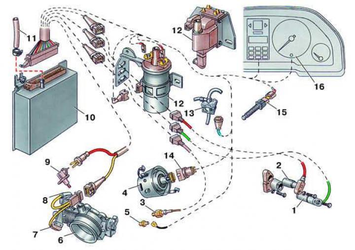
- 1 - crankshaft speed sensor;
- 2 - ignition timing sensor;
- 3 - knock sensor;
- 4 - ignition distributor;
- 5 - thermal switch;
- 6 - idle speed stabilizer;
- 7 - idle mode switch;
- 8 - Full throttle open switch;
- 9 - air temperature sensor;
- 10 - control unit;
- 11 - vacuum tube;
- 12 - ignition coil;
- 13 - bypass valve;
- 14 - connecting block;
- 15 - brake pedal position sensor (for cars with automatic transmission);
- 16 - instrument cluster
Checking the resistance of the secondary winding of the first type ignition coil
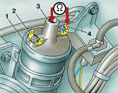
- 1 - ignition coil;
- 2 - terminal "1";
- 3 - high voltage terminal;
- 4 - terminal "15"
Suspension of connecting pads on a bracket
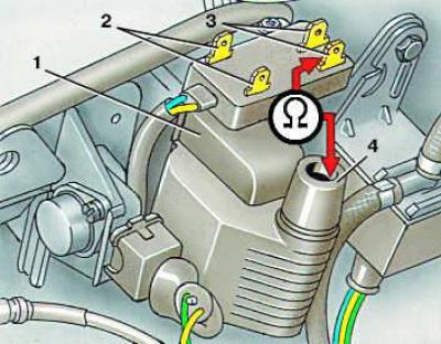
- 1 - ignition timing sensor block; black color;
- 2 - Crankshaft speed sensor block; gray color;
- 3 - knock sensor block; red color;
- 4 - terminal "4"
The ignition coil installed on a car can be of two types.
Execution order
1. Disconnect the high-voltage and low-voltage wires from the ignition coil.
2. Connect an ohmmeter and measure the resistance of the secondary winding. It should be 6.8 kOhm for the first type coil, 7.7 kOhm for the second type coil.
3. Connect an ohmmeter to terminals 2 and 4 or 2 and 3 and measure the resistance of the primary winding. It should be 0.5–1.5 ohms for both types of coils.
4. If the resistance of the secondary and primary windings differs from the specified value, the coil must be replaced.
(The original article is available on the online resource: AUDIMANUAL.RU)