Repair Chevrolet Repair Toyota Repair Honda Repair AvtoVAZ Repair Mercedes-Benz Repair BMW Repair Opel
Home  |  Contacts  |  Sitemap  |    
English Русский
Български
Беларускі
Український
Српски
Hrvatski
Română
Polski
Slovenský
Magyar
AudiManual.ru


  • AUDI 80
  • AUDI 100
  • AUDI A3
  • AUDI A4
  • AUDI A6
  • AUDI A8
  • AUDI Q
  • OTHER
  • ARTICLES
B8 (2007-2015) B7 (2004-2008) B6 (2000-2006) B6 (2000-2006, petrol) B5 (1994-2001) B5 (1994-2001, petrol)

High Voltage Ignition Coil — Removal, Checking and Installation (Audi A4 B5)

  • Home
  • Audi A4
  • B5 (1994-2001)
  • Power unit
  • Ignition system
  • High Voltage Ignition Coil — Removal, Checking and Installation
            0
Table of contents: Removal ↓ Examination ↓ Installation ↓

Removal


1. On ADP engines, the ignition coil is mounted on the right side of the firewall, at the rear of the engine compartment. On ADR, AFY, APT and APW engines, the coil is mounted on the valve cover, above the spark plugs of the third and fourth cylinders. The spark plug wires of these cylinders are integrated into the coil, the wires of the first and second cylinders are conventional. On AHL engines, the ignition coil is mounted in the center of the firewall at the rear of the engine compartment. On AEB and AJL engines, four high-voltage coils are mounted directly on the spark plugs.

2. On ADP and AHL engines, disconnect the low voltage wiring connector from the coil on the firewall, then disconnect the high voltage wire. Remove the coil from the firewall.

3. On ADR. AFY, APT and APW engines, remove the top engine cover, lift the retainer and disconnect the wiring connector. Unscrew the nut and disconnect the ground wire. Carefully pull the high-voltage wires off the spark plugs of cylinders 1 and 2, holding the tip, but not the wire itself. Unscrew the mounting nuts and remove the coil, simultaneously pulling the high-voltage wires off the spark plugs of cylinders 3 and 4 (fig. 3.3, e-g). Remove the gasket.

3. On ADR. AFY, APT and APW engines, remove the top engine cover, lift the retainer and disconnect…

3. On ADR. AFY, APT and APW engines, remove the top engine cover, lift the retainer and disconnect…

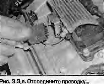
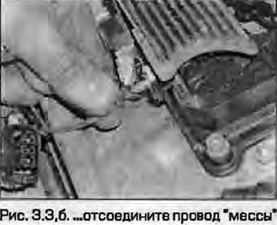
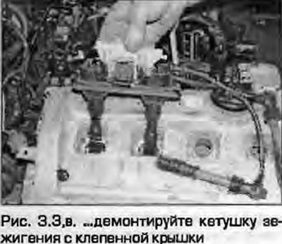
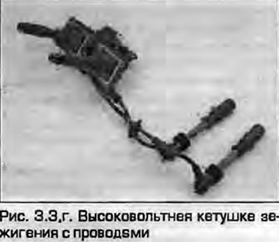
4. On AEB and AJL engines, remove the top engine cover, disconnect the wiring from all four coils. Unscrew the bolt and disconnect the ground wire from the valve cover and move the wiring to the side. Unscrew the mounting bolts and carefully remove the coils from the valve cover, simultaneously disconnecting the high-voltage terminals from the spark plugs. Remove the gaskets from the coils. The high-voltage terminals can be removed from the coils.


Examination


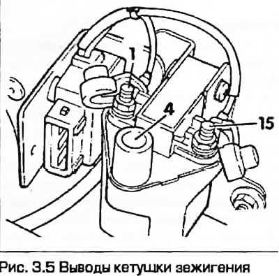
5. On ADP and AHL engines, disconnect the low voltage wiring connector and connect an ohmmeter between the two low voltage terminals of the coil (pins 1 and 15). Check that the resistance of the primary winding matches the data given in Specifications. Now check the secondary winding resistance by connecting an ohmmeter between terminals 4 (high voltage) and 15 data given in Specifications (Fig. 3.5).

5. On ADP and AHL engines, disconnect the low voltage wiring connector and connect an ohmmeter…


6. On ADR, AFY, APT and APW engines it is not possible to test the coil assembly, but you can test the power supply at the low voltage connector by connecting a tester between the center terminal and ground. Turn on the ignition - the voltmeter should register battery voltage.

7. On AEB and AJL engines, the best method of checking is to replace the coil with a known good one. Using another method, disconnect the wiring from the injectors one by one, identifying the faulty cylinder. Having identified the faulty cylinder, remove the spark plug from it and check it. If the spark plug is in good condition and is able to ensure normal engine operation, the suspicion falls on the coil, which should be replaced. Coils can be interchanged.


Installation


8. Installation - reverse procedure. To secure the wiring connector on ADR, AFY, APT and APW engines, press the lock.

(The original article is available on the website: AUDIMANUAL)
The article was checked by auto expert Timur Bazhenov
This article is available at russian, bulgarian, belarusian, ukrainian, serbian, croatian, romanian, polish, slovak, hungarian

Share information:
Previous articles
Audi A4 B5: Ignition system
Next articles

Ignition system — check
Ignition system — general information
Ignition System Specifications
Distributor — removal, inspection and installation
Ignition timing — checking and adjustment
Ignition system sensors — removal and installation
Runner — removal and installation


Similar articles on other Audi car models:
Ignition distributor — checking, removal and installation Audi 80 B4 (1991-1996)
High pressure fuel pump — removal, installation and adjustment Audi 100 C3 (1982-1990, diesel)
Removal, installation and checking the clutch Audi A3 Type 8L (1996-2003)
Electrical diagram of high voltage circuit, ignition coil, spark… Audi A6 C5 (1997-2004)
Removal and installation the engine Audi A8 D2 (1994-2002)
Turbocharger — removal and installation Audi Q5 Type 8R (2008-2017)
Removal and installation the high-tone speaker Audi A2 (1999-2005)
Link to this page in different formats


Visitor comments

No comments yet


How much will 43 + 24 =


A4(B8, 2007-2015) 
  • General information
  • Operating instructions
  • Power unit
  • Petrol engines 1.8 l
  • Petrol engines 1.8/2.0 l
  • Petrol engines 3.0 l
  • Petrol engines 3.2 l
  • Fuel system (petrol)
  • Diesel engines 2.0 l (CA*)
  • Diesel engines 2.0 l (CJCB)
  • Diesel engines 2.7/3.0 l
  • Diesel engines 3.0 l
  • Fuel system (diesel)
  • Transmission
  • Manual gearbox 0B1
  • Manual gearbox 0B2
  • Manual gearbox 0B3
  • Manual gearbox 0B4
  • Automatic transmission 0B5
  • Automatic transmission 0B6
  • Automatic transmission 0AW
  • All-wheel drive system
  • Chassis
  • Front suspension
  • Rear suspension
  • Brake system
  • Steering system
  • Body
  • Exterior
  • Interior
  • Seats
  • Doors, locks and windows
  • Security system
  • Heating and air conditioning
  • Electrical equipment
  • Audio system
  • Power devices
  • Equipment and devices
  • Lighting and lamps
  • Electrical circuits
 
A4(B7, 2004-2008) 
  • General information
  • Introduction to manual
  • Troubleshooting
  • Operating instructions
  • Maintenance
  • Power unit
  • Petrol engines 2.0 (ALT)
  • Petrol engines 2.0 (TFSI)
  • Petrol engines 1.8 (MPI)
  • Diesel engines
  • Cooling system
  • Air conditioner
  • Fuel and exhaust system
  • Ignition system
  • Starting and charging
  • Transmission
  • Clutch
  • Manual gearbox
  • Automatic gearbox
  • Drive shafts
  • Chassis
  • Brake system
  • Front suspension
  • Rear suspension
  • Steering
  • Body
  • Exterior
  • Interior
  • Electrical equipment
  • Equipment and devices
  • Lighting and signaling
  • Windscreen wipers and washers
  • Electrical diagrams
  • Electrical diagrams (since 2007)
 
A4(B6, 2000-2006) 
  • General information
  • Vehicle Description
  • User manual
  • Maintenance
  • Power unit
  • Gasoline engine
  • Diesel engine
  • Lubrication system
  • Cooling system
  • Supply system
  • Injection system
  • Exhaust system
  • Ignition and control
  • Transmission
  • Gear box
  • Clutch and drive shafts
  • Chassis
  • Brake system
  • Car suspension
  • Steering
  • Body
  • Heating and ventilation
  • Exterior (external elements)
  • Interior (internal elements)
  • Electrical equipment
  • Power devices
  • Lighting and appliances
  • Electrical circuits
 
A4(B6, 2000-2006, petrol) 
  • General information
  • Introduction to the guide
  • Car care
  • Power unit
  • Engine repair
  • Lubrication system
  • Cooling system
  • Injection and control system
  • Ignition system
  • Power and exhaust system
  • Transmission
  • Clutch and drive shafts
  • Car gearbox
  • Chassis
  • Suspension and wheels
  • Steering
  • Brake system
  • Body
  • Interior
  • Exterior
  • Electrical equipment
  • Equipment and devices
  • Lighting and signaling
  • Power devices
  • Electrical circuits
 
A4(B5, 1994-2001) 
  • General information
  • Introduction to the guide
  • Car care
  • Maintenance (gasoline)
  • Maintenance (diesel)
  • Power unit
  • Gasoline engines
  • Diesel engines
  • Engine overhaul
  • Cooling system
  • Fuel injection (gasoline)
  • Fuel system (diesel)
  • Exhaust system
  • Ignition system
  • Transmission
  • Clutch
  • Mechanical gearbox
  • Automatic gearbox
  • Drive shafts
  • Chassis
  • Brake system
  • Car suspension
  • Steering
  • Body
  • Exterior
  • Interior
  • Doors, locks and windows
  • Heating and ventilation
  • Electrical equipment
  • Power devices
  • Equipment and devices
  • Electrical circuits
 
A4(B5, 1994-2001, petrol) 
  • General information
  • Vehicle description
  • Maintenance
  • Power unit
  • Engine repair
  • Turbocharging
  • Exhaust system
  • Cooling system
  • Ignition system
  • Fuel system
  • Motronic injection system
  • MPI and MPFI injection system
  • Transmission
  • Clutch
  • Gearbox and shafts
  • Chassis
  • Steering
  • Car suspension
  • Brake system
  • Wheels and tires
  • Body
  • Heating and ventilation
  • Body parts
  • Electrical equipment
  • Fuses and relays
  • Power devices
  • Lighting and lamps
  • Tools and devices
  • Electrical circuits
 
AudiManual.ru © 2017-2026 · Mobile version · Feedback · Sitemap: EN BG BY UA RS HR RO PL SK HU · Site search · News and articles
80 B2 · 80 B3 petrol · 80 B3 · 80 B4 · 100 C3 diesel · 100 C3 petrol · 100 C3 · 100 C4 petrol · 100 C4 · A3 Type 8L · A4 B5 petrol · A4 B5 · A4 B6 petrol · A4 B6 · A4 B7 · A4 B8 · A6 C4 · A6 C5 · A6 C5 Allroad · A8 D2 · Q5 Type 8R · Q7 Typ 4L · Audi A2 ·
This site uses cookies 🍪. Click the button to accept this fact.