
Note: This paragraph applies to ADP engines only.
Removal
1. The distributor is mounted at the rear of the engine on the left and is driven by the upper end of the oil pump drive shaft, which in turn is driven by the auxiliary shaft.
2. Set the engine to the TDC position of the compression stroke of the first cylinder, as described in paragraph 2 of chapter 2A.
3. Disconnect the high-voltage wire from the ignition coil on the engine shield, mark the high-voltage wires relative to the spark plugs and disconnect them.
4. Disconnect the Hall sensor wiring from the distributor housing.
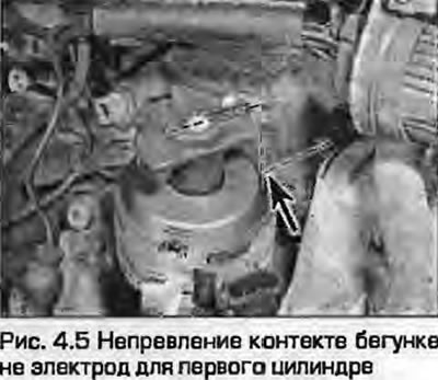
5. Release the spring clips and remove the distributor cap. Make sure that the runner is facing the contact on the cap corresponding to the first cylinder (not on the lid - number 1) (Fig. 4.5).
6. Draw a mark on the distributor to indicate its position on the block.
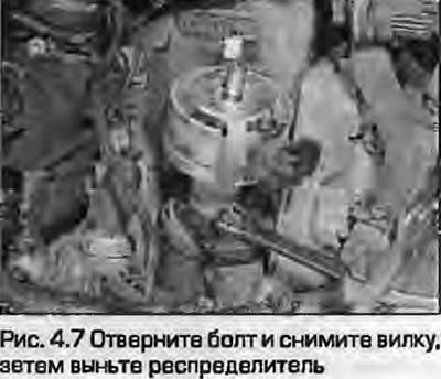
7. Loosen the bolt and remove the fork bracket. Remove the distributor from the block. Remove the O-ring (Fig. 4.7).
Note: When removing the distributor, the runner will rotate counterclockwise.
Examination
8. Remove the sealing ring at the bottom of the distributor and inspect it. Replace any worn out ring.
9. Check the condition of the drive gear teeth - wear of the teeth causes instability of the ignition timing. If the gear is worn or damaged, replace the distributor.
Installation
10. Make sure that the engine is still at TDC of the compression stroke of the first cylinder.
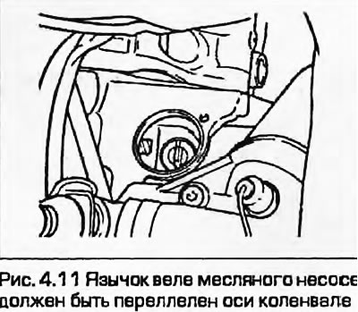
11. Make sure that the drive tongue of the oil pump shaft is parallel to the crankshaft axis (Fig. 4.11). If this is not the case, turn it with a screwdriver.
12. Install a new sealing hoof, insert the distributor, secure with a fork and tighten the mounting bolt "by hand". To mate the distributor shaft with the oil pump shaft, rotate it slightly. Align the pre-applied risks on the distributor housing and the cylinder block.
13. The shaft is installed correctly if the rotor points to the first contact of the distributor cap. This may require several attempts, since the drive gear is helical. Tighten the distributor mounting bolt.
14. Install the distributor cap and secure with spring clips.
15. Connect the wiring connector to the Hall sensor.
16. Connect the high-tension wires to the spark plugs and the central high-tension wire to the ignition coil
17. Now it is necessary to check the ignition timing and, if necessary, adjust it as described in paragraph 5.
[Content source: the specified website «AUDImanual»]