
Suspension of connecting pads on a bracket
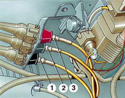
- 1 - ignition timing sensor block; black color;
- 2 - Crankshaft speed sensor block; gray color;
- 3 - knock sensor block; red color
Checking the gap between the ignition timing sensor and the flywheel
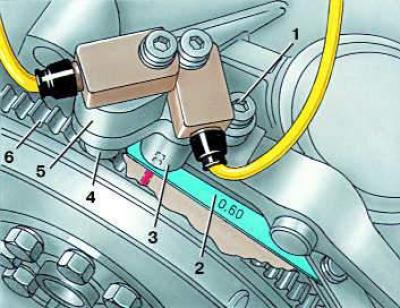
- 1 - bracket mounting bolt;
- 2 - feeler gauge;
- 3 - ignition timing sensor;
- 4 - crankshaft speed sensor;
- 5 - sensor mounting bracket;
- 6 - flywheel
Checking the gap between the crankshaft speed sensor and the flywheel
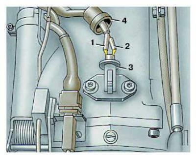
- 1 - feeler gauge;
- 2 - crankshaft speed sensor;
- 3 - flywheel;
- 4 - protective cap
Removal and installation
1. Disconnect the pads.
2. Unscrew the bolt and remove the bracket with sensors.
3. Remove the transmission to gain access to the engine flywheel.
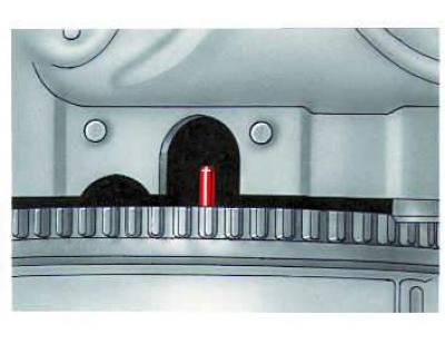
4. Turn the crankshaft so that the pin on the flywheel appears in the cutout for the sensor.
5. Install the bracket with the sensor in place and use a feeler gauge to measure the gap between the flywheel pin and the ignition timing sensor and the gap between the crankshaft speed sensor and the flywheel.
6. The gap between the pin and the ignition timing sensor should be 0.45–1.25 mm, and between the flywheel and the speed sensor – 0.51–1.24 mm.
7. If the measured gaps differ from those specified, replace the sensor bracket. You can also put shims under to increase the gaps or grind the bracket to reduce them.