
Table of contents: Operating principle ↓ Operation of the injection system… ↓ Cold engine start ↓ Enriching the mixture in… ↓ Enrichment of the mixture at full… ↓ Forced idle ↓
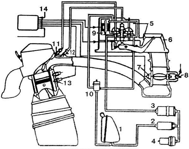
Fuel injection system diagram "KE-Jetromic": 1 - fuel tank; 2 - fuel pump; 3 - fuel filter; 4 - fuel storage tank; 5 - fuel dispenser, 6 - air flow meter; 7 - throttle limit switch 8 - additional air supply valve; 9 - electro-hydraulic control pressure regulator; 10 - fuel pressure regulator in the system; 11 injector, 12 - starting injector. 13 - coolant temperature sensor; 14 - electronic control unit
Operating principle
Fuel under pressure is constantly supplied to the injectors 11 (see diagram), installed in front of the intake valves. The injector sprays fuel, the amount of which is determined by its pressure and depending on the load (from vacuum in the intake manifold) and from the temperature of the coolant.
The fuel quantity is regulated by a metering distributor 5, controlled by an air flow meter 6, and an electrohydraulic control pressure regulator 9, controlled by an electronic unit 14 based on signals from a coolant temperature sensor 13, a throttle limit switch 7 and an engine speed sensor, as well as depending on the engine crankshaft speed.
Operation of the injection system under load and idle conditions
Electric fuel pump 2 takes fuel from the tank and delivers it under pressure to the dispenser-distributor 5 through the accumulator 4 and fuel filter 3.
Fuel enters the upper chambers of the dispenser-distributor under pressure, which is varied by regulator 10 depending on the position of the distribution plunger. The amount of fuel supplied to the injectors is regulated by a diaphragm pressed by the control pressure to the outlet openings. The control pressure regulator is an electric valve controlled by an electronic unit. In load modes, the valve occupies the working position.
The additional air supply valve is installed in the air channel, made parallel to the throttle valve, the opening of which is regulated by a conical screw. This valve maintains a minimum vacuum in the air flow meter area and provides an additional amount of air to the engine when the engine is idling. The engine idle speed is regulated automatically by an electromagnetic regulator controlled by an electronic unit.
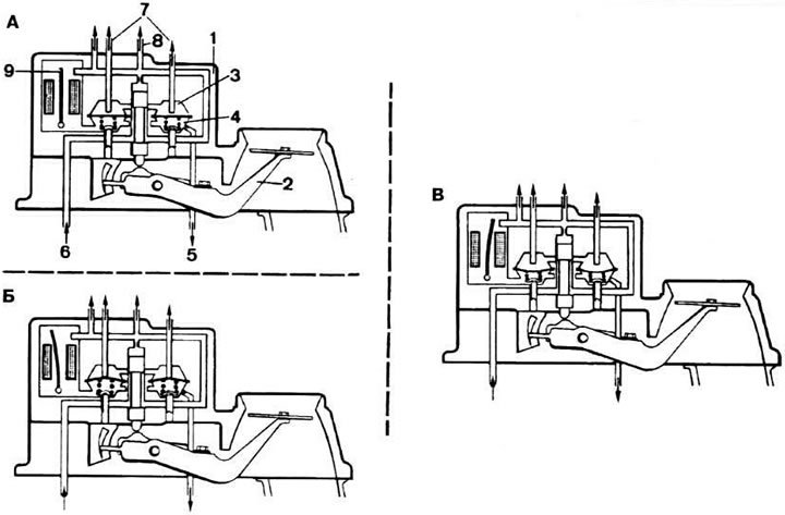
The operating principle of the fuel dispenser: A - at operating modes of the engine; B - at forced idle; B - when starting a cold engine and accelerating; 1 - dispenser-distributor body; 2 - air flow meter pressure disk lever; 3 - upper chamber; 4 - lower chamber; 5 - fuel slip into the tank; 6 - fuel supply; 7 - fuel supply pipes to the injectors; 8 - fuel supply pipe to the starting injector; 9 - bimetallic spring
Cold engine start
The electric pump instantly creates pressure in the system. When the engine starts and for a certain time, depending on the temperature of the coolant, the starting injector 12 sprays fuel under pressure in the intake manifold, which ensures the start of a cold engine.
The additional air supply valve 8 opens access to the intake manifold for additional air, thereby increasing the crankshaft speed at idle. The mixture enrichment on a cold engine is carried out by the control pressure regulator, which reduces it by the amount necessary to increase the amount of fuel. After the engine warms up to operating temperature, the mixture enrichment stops.
Enriching the mixture in acceleration mode
When the throttle valve is opened, the mixture is enriched in a similar manner by reducing the control pressure supplied by regulator 9 depending on the speed of the throttle valve.
Enrichment of the mixture at full load mode
At full engine load, the combustible mixture is enriched by commands from the electronic control unit based on information from the throttle valve limit switch.
Forced idle
When the throttle valve is closed, when the engine crankshaft speed exceeds 1700 rpm, the control pressure regulator opens completely and a pressure equal to the fuel supply pressure is created in the lower chambers of the fuel distributor. The fuel supply to the injectors is converted.
(The original version of the article is posted on the website AudiManual.ru)