Repair Chevrolet Repair Toyota Repair Honda Repair AvtoVAZ Repair Mercedes-Benz Repair BMW Repair Opel
Home  |  Contacts  |  Sitemap  |    
English Русский
Български
Беларускі
Український
Српски
Hrvatski
Română
Polski
Slovenský
Magyar
AudiManual.ru


  • AUDI 80
  • AUDI 100
  • AUDI A3
  • AUDI A4
  • AUDI A6
  • AUDI A8
  • AUDI Q
  • OTHER
  • ARTICLES
C4 (1990-1994) C4 (1990-1994, petrol) C3 (1982-1990) C3 (1982-1990, petrol) C3 (1982-1990, diesel)

Checking the coolant temperature gauge sensor (Audi 100 C3)

  • Home
  • Audi 100
  • C3 (1982-1990)
  • Electrical equipment
  • Lighting and appliances
  • Checking the coolant temperature gauge sensor
            0
If the engine overheats in models with gasoline engines (the coolant temperature gauge needle is in the red zone) the coolant overheating lamp does not light, you need to check the coolant temperature gauge sensor.

If the coolant temperature gauge needle does not move to the right when the engine overheats in diesel models, the coolant temperature gauge sensor needs to be checked.

Execution order


1. Disconnect the wiring harness from the coolant temperature sensor.

Models with petrol engines


2. Short the yellow-blue wire to ground using an additional wire and turn on the ignition. If the coolant temperature indicator light on the instrument cluster lights up, the sensor is faulty and needs to be replaced.

3. If the lamp does not light, check it. To do this, remove the instrument cluster (see subsection 12.1.5.15).

3. If the lamp does not light, check it. To do this, remove the instrument cluster (see subsection…


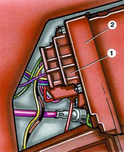
4. If the lamp has not burned out, check the electrical circuit. To do this, disconnect the wire from the negative terminal of the battery. Then disconnect the 12-pin connector (1) from the instrument cluster (2) and check the circuit resistance with an ohmmeter by connecting it to contact "2" of connector 1 and the yellow-blue wire connected to the sensor. The resistance should be zero. If it is infinity, there is a break in the circuit.


Models with diesel engines


5. Short the yellow-blue wire to ground using an additional wire and turn on the ignition. If the coolant temperature gauge needle on the instrument cluster moves to the right, the sensor is faulty and must be replaced.

6. If the pointer does not move to the right, you need to check the electrical circuit. To do this, disconnect the wire from the negative terminal of the battery. Then disconnect the 12-pin connector from the instrument cluster and check the circuit resistance with an ohmmeter, connecting it to contact "2" of the connector and the yellow-blue wire connected to the sensor. The resistance should be zero; if it is infinity, there is a break in the circuit.

7. If there is no break in the circuit, then the fuel level indicator is faulty and needs to be replaced.
The article was checked by auto expert Daniil Ushakov
This article is available at russian, bulgarian, belarusian, ukrainian, serbian, croatian, romanian, polish, slovak, hungarian

Share information:
Previous articles
Audi 100 C3: Lighting and appliances
Next articles

Checking the reverse light switch
Removal and installation the turn signal relay
Checking the voltage stabilizer
Removal and installation the instrument cluster
Checking the fuel gauge
Adjusting the fuel gauge
Removal and installation the windshield wiper


Similar articles on other Audi car models:
Coolant Temperature Sensor — Removal and Installation Audi 80 B3 (1986-1991, petrol)
Checking the oil pressure and oil pressure gauge sensor Audi A3 Type 8L (1996-2003)
Cooling system — coolant pipes, coolant temperature sensor,… Audi A4 B8 (2007-2015)
Electrical diagram of the Motronic control unit, valve… Audi A6 C5 (1997-2004)
Checking the ABS sensor rotor Audi A8 D2 (1994-2002)
Removal the coolant temperature sensor Audi Q5 Type 8R (2008-2017)
Removal and installation coolant temperature sensor G62 Audi A2 (1999-2005)
Link to this page in different formats


Visitor comments

No comments yet


How much will 38 + 25 =


100(C4, 1990-1994) 
  • General information
  • User manual
  • Power unit
  • Engine repair
  • Ignition system
  • Fuel system (gasoline)
  • Fuel system (diesel)
  • Lubrication system
  • Cooling system
  • Exhaust system
  • Transmission
  • Clutch
  • Car gearbox
  • Drive shafts
  • Chassis
  • Car suspension
  • Steering
  • Wheels and tires
  • Brake system
  • Body
  • Ventilation and heating
  • Body repair
  • Electrical equipment
  • Power devices
  • Lighting and appliances
  • Electrical circuits
 
100(C4, 1990-1994, petrol) 
  • General information
  • Operation and maintenance
  • Power unit
  • Engine repair
  • Exhaust system
  • Cooling system
  • Supply system
  • Air filter
  • Mono-Motronic injection system
  • Digifant injection system
  • KE-III-Jetronic and KE-Motronic
  • MPI and MPFI injection system
  • Transmission
  • Clutch
  • Car gearbox
  • Chassis
  • Suspension and steering
  • Brake system
  • Wheels and tires
  • Body
  • Exterior
  • Interior
  • Electrical equipment
  • Fuses and relays
  • Power devices
  • Ignition system
  • Lighting and signaling
  • Equipment and devices
  • Electrical circuits
 
100(C3, 1982-1990) 
  • General information
  • User manual
  • Maintenance
  • Specifications
  • Power unit
  • Engines 4-cylinder
  • Engines 5-cylinder
  • Diesel engine
  • Cooling system
  • Power system (carburetor)
  • Power system (injector)
  • Fuel system (diesel)
  • Transistor ignition system
  • Electronic ignition system
  • Transmission
  • Clutch
  • 4 speed gearbox 014
  • 5 speed gearbox 013 and 093
  • 5 speed gearbox 016 and 012
  • Shift mechanism KP 016
  • Automatic transmission
  • Front wheel drive
  • Chassis
  • Front suspension
  • Rear suspension
  • Steering
  • Brake system
  • Body
  • Body elements
  • Electrical equipment
  • Lighting and appliances
  • Power devices
  • Electrical circuits
 
100(C3, 1982-1990, petrol) 
  • General information
  • Maintenance and operation
  • 4 cylinder engine
  • Engine repair
  • Cooling and lubrication system
  • Supply system
  • Ignition system
  • 5 cylinder engine
  • Engine repair
  • Cooling and lubrication system
  • Supply system
  • Ignition system
  • Transmission
  • Clutch and drive shafts
  • 4 speed gearbox 014
  • 5 speed gearbox 013 and 093
  • 5 speed gearbox 016 and 012
  • Automatic gearbox
  • Chassis
  • Steering
  • Front suspension
  • Rear suspension
  • Brake system
  • Body
  • Body elements
  • Doors, locks and windows
  • Body repair
  • Electrical equipment
  • Equipment and devices
  • Power devices
  • Electrical circuits
 
100(C3, 1982-1990, diesel) 
  • General information
  • User manual
  • Maintenance
  • Troubleshooting
  • Power unit
  • Engine in a car
  • Engine removed
  • Cooling system
  • Fuel system
  • Exhaust system
  • Starting and charging
  • Preheating
  • Transmission
  • Clutch
  • Mechanical gearbox
  • Automatic gearbox
  • Drive shafts
  • Chassis
  • Brake system
  • Suspension
  • Steering
  • Body
  • Exterior
  • Interior
  • Electrical equipment
  • Equipment and devices
  • Electrical circuits
 
AudiManual.ru © 2017-2026 · Mobile version · Feedback · Sitemap: EN BG BY UA RS HR RO PL SK HU · Site search · News and articles
80 B2 · 80 B3 petrol · 80 B3 · 80 B4 · 100 C3 diesel · 100 C3 petrol · 100 C3 · 100 C4 petrol · 100 C4 · A3 Type 8L · A4 B5 petrol · A4 B5 · A4 B6 petrol · A4 B6 · A4 B7 · A4 B8 · A6 C4 · A6 C5 · A6 C5 Allroad · A8 D2 · Q5 Type 8R · Q7 Typ 4L · Audi A2 ·
This site uses cookies 🍪. Click the button to accept this fact.