
Table of contents: Removal ↓ Disassembly ↓ Inspection and defect detection of… ↓ Assembly ↓ Installation ↓
The cars are equipped with independent McPherson type front suspension with transverse levers and anti-roll bar. Telescopic strut with double-acting hydraulic shock absorbers and coil springs. The all-wheel drive suspension features a negative camber angle.
Front suspension elements
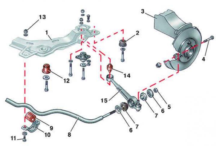
- 1 - front suspension beam;
- 2 - rear rubber bushing;
- 3 - steering knuckle;
- 4 - bolt;
- 5 - nut;
- 6 - pillow plate;
- 7 - pillow;
- 8 - transverse stability stabilizer bar;
- 9 - pillow;
- 10 - pillow clip;
- 11 - bolt;
- 12 - Front rubber bushing;
- 13 - nut;
- 14 - rubber bushing;
- 15 - suspension arm
Telescopic stand
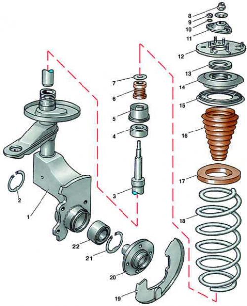
- 1 - steering knuckle;
- 2 - retaining ring;
- 3 - shock absorber;
- 4 - lower mounting nut
- shock absorber;
- 5 - protective cap;
- 6 - compression stroke buffer;
- 7 - washer;
- 8, 9 - nuts;
- 10 - washer;
- 11 - upper support of the rack;
- 12 - base of the upper support;
- 13 - bearing;
- 14 - upper spring cup;
- 15 - protective ring;
- 16 - protective cover;
- 17 - rubber gasket;
- 18 - spring;
- 19 - brake shield;
- 20 - hub;
- 21 - retaining ring;
- 22 - hub bearing
Removal
1. Apply the parking brake to the vehicle and place chocks under the rear wheels.
2. Loosen the front wheel mounting bolts and unscrew the axle shaft mounting nut.
3. Raise and support the front of the vehicle.
4. Finally, loosen the mounting bolts and remove the front wheel.
5. Loosen the mounting bolts and remove the stabilizer bar cushion clips.
6. Loosen the two mounting bolts, remove the brake caliper assembly and hang it on a wire to the body, making sure that the brake hose does not twist or experience excessive loads. For ease of subsequent installation of the brake caliper, it is recommended to first remove the brake pads (see subsection 10.5).
7. Remove the brake disc (see subsection 10.6).
8. Loosen the nut and remove the bolt securing the ball joint pin of the suspension arm to the steering knuckle. Using a pry bar, carefully, so as not to damage the mudguard of the joint, remove the ball joint pin from the clamp of the steering knuckle, thereby disconnecting the suspension arm from the steering knuckle.
9. Loosen the mounting nut and press out the ball joint pin of the steering rod from the steering arm, thereby disconnecting the steering rod from the rack.
10. Press the axle out of the hub using a puller.
11. Remove the decorative cap that covers access to the upper shock absorber mounting nut.
12. Unscrew the three nuts securing the base of the upper support to the body, holding the telescopic stand from below.
13. Remove the telescopic stand from the vehicle.
Disassembly
1. Compress the spring using a special device.
2. Loosen the upper shock absorber mounting nut while holding the shock absorber rod from turning using a hex key.
3. Remove all parts of the telescopic stand one by one.
4. Remove the protective cap.
5. Using a special tool, unscrew the lower shock absorber mounting nut (at service stations, the 2069 device is used).
6. Remove the shock absorber.
Inspection and defect detection of shock absorbers
1. Clean the shock absorber from dirt.
2. Inspect the shock absorber rod. If the rod is bent or there is peeling of the chrome coating on the working surface, traces of corrosion, scoring, damage to the threaded part, then the shock absorber must be replaced.
3. Set the shock absorber in a vertical position. Check the condition of the shock absorber by moving the piston by the rod along the entire length of the stroke.
4. If jamming or lack of resistance is detected during the piston stroke, and there are also clear signs of fluid leakage through the seal, the shock absorber must be replaced. Traces of fluid fogging are acceptable.
5. Clean the spring from dirt and check it thoroughly. If there are cracks or deformation of the coils, replace the spring.
6. Replace the defective rubber gasket.
Assembly
1. Install the shock absorber on the steering knuckle and tighten the lower shock absorber mounting nut using a special tool to a torque of 180 N·m (18.0 kgf·m).
2. Install the protective cap.
3. Compress the spring using a special device.
4. Install the telescopic strut parts in reverse order. Insert the lower end of the spring into the recess of the lower cup until it stops.
5. Rubber gaskets are supplied in spare parts of different thickness: with one mark - 19 mm, with two marks - 15 mm, with three marks - 9 mm. When replacing the spring, it is recommended to install a gasket with two marks.
6. Tighten the upper shock absorber mounting nut to a torque of 60 N·m (6.0 kgf·m), holding the shock absorber rod from turning with a hex key.
7. Release the spring.
Installation
1. Clean the hub and axle splines from dirt and residues of special glue and wipe them with gasoline.
2. Apply special D6 glue to the axle shaft splines (only on models produced before January 1988 and on models with automatic transmission) to a length of 5-6 mm from the end of the splined part. After this, a test drive can only be made after 60 minutes to allow the glue to harden.
3. At the same time, insert the studs of the upper strut mount into the holes in the body and place the hub on the splines of the axle shaft.
4. Tighten the three new upper strut mounting nuts to a torque of 30 N·m (3.0 kgf·m).
5. Insert the ball joint pin of the suspension arm into the clamp of the steering knuckle and tighten the new mounting bolt with a new nut to a torque of 65 N·m (6.5 kgf·m).
6. Press the ball joint pin of the steering rod into the steering arm and tighten the new fastening nut to a torque of 60 N·m (6.0 kgf·m).
7. Install the brake disc.
8. Install the brake caliper.
9. Raise the stabilizer bar, install the cushion clips and tighten their mounting bolts with new nuts to a torque of 105 N·m (10.5 kgf·m).
10. Install the wheel and tighten the mounting bolts.
11. Fit a new hub mounting nut (on models produced after January 1988 – a special bolt).
12. Lower the car onto its wheels.
13. Tighten the axle shaft nut to 280 N·m (28.0 kgf·m). On models produced after January 1988, tighten the special bolt to 200 N·m (20.0 kgf·m), then tighten it an additional quarter turn (90°).
14. Tighten the wheel mounting bolts evenly to a torque of 110 N·m (11.0 kgf·m).
15. Check the wheel alignment at a service station.
| Color markings on springs | Car models |
|
White
|
4-cylinder cars with conventional suspension
|
|
Brown
|
Cars with 4-cylinder engines with front springs
large diameter pendants
|
|
Orange
|
4-cylinder engine vehicles with reinforced suspension
|
|
Silvery
|
Cars with 5-cylinder engines
|
|
Yellow
|
Cars with 5-cylinder engines in CD version
|
|
Green
|
Cars with 5-cylinder engines with reinforced suspension
|
|
Blue
|
Cars with 5-cylinder engines in CD version
with reinforced suspension
|
[Material republished from the website: audimanual.ru]