
Table of contents: Switches and controls located on the… ↓ Multifunctional steering wheel and… ↓ Controls located in the doors ↓ Controls located on the instrument… ↓ Controls and equipment on the center… ↓ Seat controls and equipment ↓ Controls and equipment located on… ↓ Equipment of the luggage compartment ↓
The location of the controls and equipment in the cabin is shown in Illustration 14.1. The components listed in this illustration are discussed below unless a section or part number is given next to them, which provides a detailed description; this section also discusses some controls not shown in Illustration 14.1.
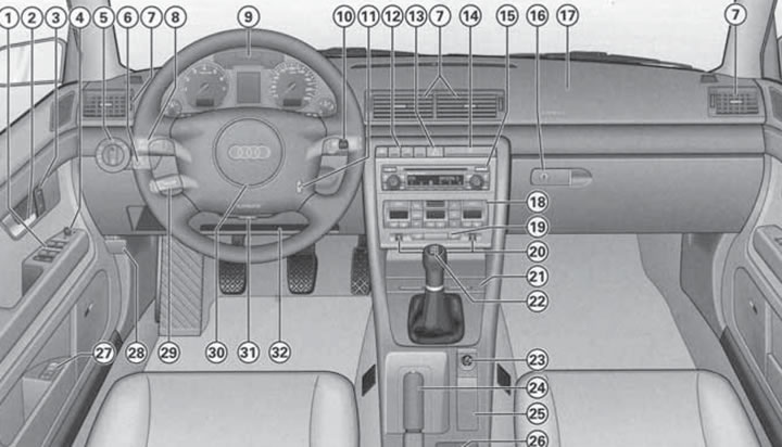
14.1. Governing bodies. 1. Window lifter control switches (see Section 6); 2. Door opening handle; 3. Keys for locking and unlocking the single lock (see Section 1); 4. Electric outside rear view mirror control switch (see Section 11); 5. External lighting control switch; 6. Headlight leveling control and headlight delay switch; 7. Deflectors with adjustable direction and flow intensity (see Section 17); 8. Left upper steering column switch; 9. Instrument cluster (see Section 15); 10. Right steering column switch; 11. Ignition switch; 12. Pencil case and/or switches of auxiliary devices; 13. Hazard warning switch; 14. Cup holder; 15. Navigation and/or audio system control unit (see Part D); 16. Main storage compartment handle and lock; 17. Front passenger airbag (see Section 12); 18. Climate control panel (see Section 17); 19. Rear window heating switch; 20. Front seat heating adjustment switches (see Section 10); 21. Ashtray; 22. Gear shift lever (manual transmission) or AT/CVT mode selector lever (see Part E); 23. 12V socket or cigarette lighter socket; 24. Parking brake lever (see Section 24); 25. Niche, or control panel for the navigation system and menu (see Sections 16 and 20); 26. Storage compartment, or a niche for storing cassettes, or a connector for connecting a laptop or fax machine; 27. Driver's seat and exterior mirror memory control panel (see Section 10); 28. Hood release handle (see Section 3); 29. Lower left steering column switch (see Section 18); 30. Steering wheel with horn switch, driver's airbag (see Section 12), audio system and telephone control keys (see Part D); 31. Steering column lock release lever (see Section 11); 32. Niche for storing a folder with documents
Switches and controls located on the steering column
Left upper steering column switch
Note: Do not leave the exterior lights on when the engine is off to avoid draining the battery.
Left steering column switch (8 in illustration 14.1) it is designed to control direction indicators, switch between low and high beam headlights, high beam headlight signaling, and also to turn on parking lights.
To turn on the left or right turn signal with the ignition on, pull the steering column stalk lever downwards or upwards, respectively, past the resistance point. The corresponding turn signal indicator light will flash in the instrument cluster (see Section 15). After completing the turn, the switch automatically returns to the neutral position. If necessary, turn off the turn signals manually by returning the lever to the neutral position.
Note: Rapid blinking of the indicator indicates a fault in the vehicle's direction indicators - check the bulbs. When towing a trailer with a faulty direction indicator bulb on the vehicle, the indicator does not turn on. When changing lanes, you can pull the switch up or down to the locking point and hold it in this position - the direction indicators will flash until the switch is released. After releasing, the switch will automatically return to the neutral position. If you pull the switch up or down to the resistance point and immediately release, the direction indicators will flash three times.
To turn on the high beam headlights (for this the low beam must be on) move the upper left steering column switch lever away from you. Turning on the high beam headlights is accompanied by the corresponding K/L in the instrument cluster (see Section 15). To turn off the high beam headlights, return the lever to its original position (pull it towards you).
To signal with high beam headlights, pull the switch lever towards you. In this position, the high beam will turn on regardless of the position of the ignition switch, and will work until the switch is released.
To turn on the side lights on one side of the vehicle after turning off the ignition, pull the left upper steering column switch lever down or up past the resistance point. To turn off the side lights, return the lever to the neutral position or turn on the ignition (the turn signals will turn on).
Right steering column switch
Note: To avoid damaging the windshield wiper mechanism, do not turn on the windshield wipers if the windshield is dry, or move them by hand. In cold weather, before turning on the windshield wipers for the first time during a trip, check that the wiper blades are not frozen. To avoid damaging the windshield wiper blades, do not allow them to come into contact with gasoline or other solvents. To avoid damaging the washer fluid supply pump, do not turn on the washer when the washer fluid reservoir is empty, or continuously for more than 30 seconds.
Note: The washer fluid nozzles are heated automatically when the ignition is on. However, do not turn on the washer if you are using regular water and the glass is cold, as this may cause the water to freeze on the glass and impair visibility. Use a special washer fluid (see Chapter 1).
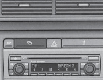
Right steering column switch (10 in illustration 14.1) is designed to control the windshield wipers and wash the glass and headlights. Additionally, this lever contains the control keys for the trip computer (see Section 16). Windscreen wipers and washers operate only when the ignition is on.
The positions of the right steering column switch and their description are shown in Illustration 14.2. On Estate models, to turn on the rear window wiper in interval mode, pull the lever away from you, and to turn on the rear window wiper and washer simultaneously, pull the lever away from you until it stops.
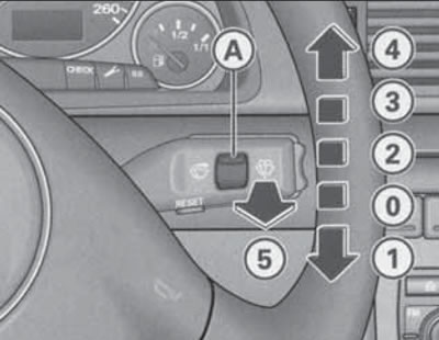
14.2. Positions of the right steering column switch
The duration of pauses in interval mode, in addition to the position of the regulator (A), depends on the speed of the vehicle.
After the windshield wiper is turned off, it will operate again after a few seconds to remove any drops that have rolled down.
After turning off the windshield wiper and windshield washer, the windshield wipers continue to operate for approximately 4 seconds. If the headlights are on, pull the lever towards you when turning on the windshield washer (in position 5) only briefly. Holding the switch pulled for more than 1 second additionally turns on the headlight washers.
To keep the headlight washer nozzles in working order in winter, they should be cleared of snow and ice using a special aerosol. Ignition switch
Ignition switch positions (11 in illustration 14.1) are shown in Illustration 14.3.
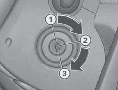
14.3. Ignition switch positions.
In position (1) the ignition is switched off, and if the ignition key is removed from the lock, the steering wheel is additionally locked.
Warning: Do not remove the key from the ignition until the vehicle has come to a complete stop, otherwise the steering wheel may lock and you may lose control. On models with AT or CVT, the key can only be removed from the ignition when the selector lever is in the "P" position. After that, the selector lever is locked together with the steering column.
In position (2), the ignition is on, all electrical devices are operational, and the steering wheel lock is released. The ignition key is also in this position after the engine has been started. If you cannot turn the key from position (1) to position (2), pull the steering wheel left/right while turning the key. If the battery has been disconnected, it is recommended to wait at least five seconds with the ignition switch in position (2) before starting the engine for the first time. On diesel engines, in position (2), the engine preheating is activated for a few seconds before starting the engine at low temperatures.
In position (3), the starter is switched on, starting the engine. When the starter is running, powerful consumers of electricity are automatically switched on, and the headlights are switched on to the parking lights. Release the key immediately after starting the engine, so as not to damage the starter - the key must return to position (2). If the ignition key was in position (3), then the next starter can only be switched on after the key is moved to position (1), i.e. after the engine is switched off. This prevents the starter from switching on and, therefore, from breaking down when the engine is running.
Multifunctional steering wheel and horn switch
The horn switch is built into the steering wheel trim. Press it without much effort, as the horn switch is integrated with the driver's front airbag.
Using the buttons located on the steering wheel spokes, you can control the audio system and turn voice control on and off (if available, see Section 20).
On CVT models on the back of the steering wheel, top (left and right), the paddle shifters are located (see Section 23).
Controls located in the doors
The doors contain compartments for small items and switches for controlling the windows (see Section 6), door opening handles and speakers. The driver's door also contains switches for controlling the outside rear-view mirrors (see Section 11), memory unit for the position of the driver's seat and rear-view mirrors (see Section 10) and the keys for unlocking/locking the single lock (see Section 1).
Controls located on the instrument panel behind the steering column
Note: Do not leave the exterior lights on when the engine is off to avoid draining the battery.
Description of the instrument cluster see Section 15.
The brightness of the instrument lighting is adjusted using the "+" keys located at the bottom of the instrument cluster (see Section 15).
Below the steering column there is a compartment for a folder with documents (32 in illustration 14.1).
To the right of the steering column is the lighting control panel, which includes the switches shown in Illustration 14.4. The switch for controlling the headlight delay function, which is installed as an additional equipment, is highlighted in this illustration.
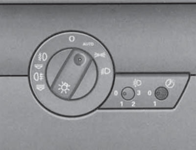
14.4. Switches in the lighting control panel.
The headlight delay function allows you to leave the exterior lights on for a while after you leave the car. This may be necessary to illuminate the road from the car to your home. To turn this function on/off, press the switch so that it protrudes from the instrument panel, turn it to the "1" or "0" position, respectively, and then press the switch so that it is flush with the instrument panel and cannot be accidentally turned. When the function is on, when the ignition is off and the headlights are on, in low light conditions, the parking lights are turned on immediately after the driver's door is opened. The level of illumination is determined by a sensor built into the housing of the interior rear-view mirror. If any door or luggage compartment is opened, the fog lights remain on for approximately 4 minutes; to illuminate the road, the fog lights remain on for another 30 seconds after the doors and luggage compartment are closed. The duration of the lighting switch-off delay is set at the factory and can be changed, if necessary, by up to 1 minute using the diagnostic tool (please contact your Audi representative to change this setting). Additionally, when the delay function is enabled, the fog lights are turned on when the car is unlocked using the remote control. They are turned off when the driver's door is opened or when the single lock is subsequently automatically locked.
Headlight leveling regulator (in the center of illustration 14.4) only available on models with halogen headlights. On models with xenon headlights, their tilt adjustment is performed automatically. To prevent the headlights from blinding oncoming drivers, the headlight tilt angle must be adjusted to the vehicle load (see Specifications). To turn the switch, first press it so that it comes out of the instrument panel. After adjustment, press the switch again so that it is flush with the instrument panel and cannot be accidentally turned.
The exterior lighting control switch occupies the left-hand position in the lighting control unit (see illustration 14.4). In position "0" the exterior lighting is off. To turn on the parking lights, turn the switch to position
Note: When starting the engine and after the ignition is turned off, the low or high beam headlights automatically switch to the parking lights. After removing the key from the ignition with the outside lights on and the driver's door open, an audible signal sounds to warn of the possibility of battery discharge if the lights are left on for a long time.
In some trim levels, the exterior lighting switch has an "AUTO" position, which is used to activate the automatic exterior lighting control function. When this function is activated, the parking lights are always on with the ignition on, and when the illumination decreases, the low beam headlights are automatically turned on. An indicator lights up in the exterior lighting switch. When the illumination exceeds a certain level, the low beam headlights are automatically turned off. The illumination is controlled by a sensor built into the front part of the interior rearview mirror housing. If the automatic system does not turn on the low beam (for example, fog and rain may not be recognized), it must be turned on manually.
To turn on the fog lights or the rear fog light, turn on the parking lights or the low/high beam headlights, and then pull the switch towards you to the first or second fixed position, respectively. Thus, when the rear fog light is turned on, the fog lights are always on. When the fog lights and the rear fog light are turned on, the corresponding indicators in the instrument cluster come on (see Section 15).
Controls and equipment on the center console and on the right side of the instrument panel
Note: Description of the climate system, entertainment system and navigation system is provided in Part D; the description of the AT/CVT mode selector or manual transmission gearshift lever, as well as the parking brake lever, is given in the relevant sections of Part E.
Cup holder (14 in illustration 14.1) it is extended and retracted by pressing on it.
Warning: When the vehicle is moving, do not place containers with hot liquid or glass containers in the cup holders, as in the event of an accident or sudden maneuvering/braking, hot liquid or heavy containers may cause burns or injuries.
Hazard warning switch (13 in illustration 14.1) works regardless of the position of the ignition switch. To turn on the hazard warning lights, press the switch button; to turn it off, press the button again. When the hazard warning lights are on, their indicators in the instrument cluster and the indicator in the switch flash synchronously with all the direction indicators.
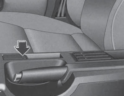
To the left of the hazard warning switch, depending on the configuration, there is a case or switches for some auxiliary devices. Description of the rear sunblind drive switch (see illustration 6.3) given in Section 6. To slide the pencil case out/in, press on it (see illustration 14.5). Parking Assistance Switch "P" (in key block 12 in illustration 14.1) is designed to turn the specified system on and off manually. Detailed information about the parking assistance system is provided in Section 19. "ESP" key (in key block 12 in illustration 14.5) is designed to force the ESP function to be turned on and off. A detailed description of this function is given in Section 24. Opposite the front passenger seat is the main storage compartment and the front passenger airbag (see Section 12). To open the main storage compartment, pull the right side of its handle (16 in illustration 14.1). If necessary, the glove box can be locked and unlocked with the car key. When the box is open and the parking lights or low/high beam headlights are on, its illumination turns on. To close the box, simply slam its lid. On the inside of the glove box lid there are fasteners for attaching writing utensils. In some configurations, a CD changer can be installed in the glove box (see Section 20) and the front passenger airbag switch (see Section 9). Also, the glove compartment can be additionally equipped with a compartment, the temperature in which can be adjusted together with the temperature adjustment of the climate control system. Thus, this compartment will be cooled when the compressor of the refrigeration unit of the climate control system is turned on, and when only the heater of the climate control system is operating, the compartment will be warm. If necessary, the air supply from the climate control system to the refrigerator of the glove compartment can be closed by turning the handle (see illustration 14.6).
14.5. Pencil case.
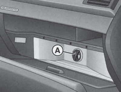
14.6. Handle for supplying air from the climate control system to the glove compartment.
The description of the front seat heating switches is presented in Section 10.
The electric rear window heating is switched on and off using the button (19 in illustration 14.1), if the ignition is on. When the heating is switched on, the indicator in the key lights up. At the same time as the rear window is heated, the heating of the outside rear-view mirrors is switched on at the appropriate outside air temperature. The rear window heating consumes a lot of energy, so it should be switched off immediately after the rear window is free of condensation or ice. If the outside air temperature is above 0°C, the heating switches off automatically 10 minutes after switching on.
The heated windshield is switched on and off using the button (In illustration 17.1), located to the right of the driver's seat heating switch if the engine is running. When the heating is turned on, the indicator in the key lights up. If the outside air temperature is less than 5°C, the engine is not warmed up and the climate control system operates in the "AUTO" mode (see Section 17), the windshield heating is switched on automatically. The duration of heating depends on the air temperature outside and does not exceed minutes. In this case, the climate control system must operate in the heating mode. In the "ECON" mode of the climate control system, the windshield heating is switched off.
Note: If a crack appears on the windshield, the windshield heating and the air conditioning system cooling unit are switched off.
A telephone can be installed on the right side of the center console (see Section 20).
To use the front ashtray (In illustration 14.7), press the front edge of its cover. To remove the ashtray, open it, grasp its side recesses and pull the ashtray upward. To install the ashtray, simply press it into the niche. The rear ashtray, covered by a cover, is located at the rear of the console between the front seats (see illustration 14.8). To remove the ashtray, open it and pull the lid upwards. To install, press the open ashtray into the niche.
Caution: Do not use the ashtray to store flammable items (for example, wrappers) if the ashtray is also used for its intended purpose.
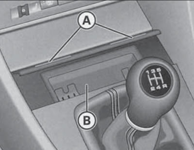
14.7. Front ashtray (B) under cover (A)
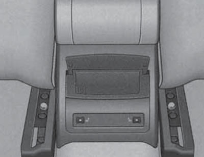
14.8. Rear ashtray
In the rear part of the center console, in addition to the ashtray, there are switches for heating the outer rear seats (see Section 10).
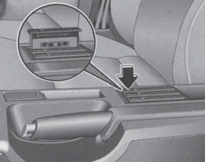
The 12V power outlet is located under the cover at the front of the panel between the seats (23 in illustration 14.1). To open the cover, press the side of the cover shown in Illustration 14.9. The socket works with the ignition on and off, and a cigarette lighter can be installed in it. To use the cigarette lighter, press it and release it. When the cigarette lighter has heated up to the required temperature, it will automatically return to its original position - remove it by holding the plastic handle. Auxiliary electrical devices can be plugged into the power socket (for example, a vacuum cleaner or a portable lamp) power up to 100 W at 12 V.
14.9. Front power socket cover.
Caution: Do not keep the cigarette lighter pressed after it is ready for use, as this may cause it to overheat; for the same reason, the cigarette lighter should be removed from its socket if it does not return to its original position automatically for a long time. An additional socket, also covered by a cover, is located in the luggage compartment (see illustration 14.10). All the comments regarding the front socket (see above) apply to this socket.
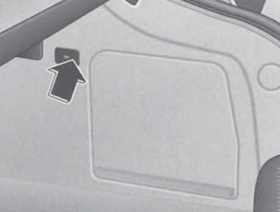
14.10. Cover for power socket in luggage compartment.
Between the front seats in the center console there is an adjustable armrest with a storage compartment (see Section 10). A cup holder for two containers can be installed in this storage box.
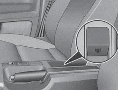
To the right of the parking brake lever, in the area (25 in illustration 14.1) depending on the configuration, there is a niche for small items, or a control panel for the navigation system and menu (see Sections 16 and 20). In the area (26 in illustration 14.1) depending on the configuration, there is a storage compartment or a niche for storing cassettes (see illustration 14.11), or a connector for connecting a laptop or fax (see illustration 14.12) with vehicle telecommunication interface (see Section 20) via a special cable. The cells of the niche for storing cassettes are used to store audio cassettes without cases (open side up). To open the cell, press the button at the front of the cell; to close, press the cell cover until it locks into place. When a cassette is installed in the cell, a red indicator appears on the left side of the cell.
14.11. Niche for storing cassettes.
Seat controls and equipment
14.12. Connector for connecting a laptop or fax.
On the outer side surfaces of the front seat cushions are seat adjustment levers or switches (see Section 10). There are storage boxes under the front seats, each of which can store items with a total weight of up to 1 kg. To open such a box, lift its handle and pull the box forward.
The backrests of the rear side seats can be folded forward to increase the volume of the luggage compartment. When the backrest of the central rear seat is folded down, a central armrest is created for rear passengers. This armrest contains a closed storage compartment and two cup holders. In some trim levels, there is a hatch with a cover for transporting long items in the backrest of the rear seat behind the armrest. All of these features are described in Section 10.
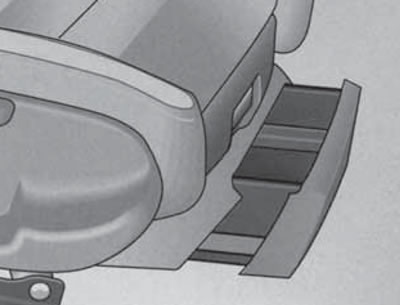
14.13. Storage compartment under the front seat
Controls and equipment located on the ceiling and windshield
A rear-view mirror is installed on the windshield (see Section 11). Depending on the configuration, various sensors may be built into the rearview mirror housing.
There are handrails and hooks for clothes on the ceiling (on the rear handrails), sun visors, overhead console and rear interior lights.
When using coat hooks, do not allow clothing to obstruct your view, and do not hang heavy objects on the hooks that could injure passengers during sudden braking or maneuvering.
The sun visors have built-in lids (1 in illustration 14.14) cosmetic mirrors. When the mirror cover is opened, the backlight located in the ceiling above the visor is turned on. On the driver's side there is also a strip for storing documents, and in some configurations - universal remote control keys (see subsection below). The visors can be folded towards the windshield and, after being released from the lock (B), towards the side window.
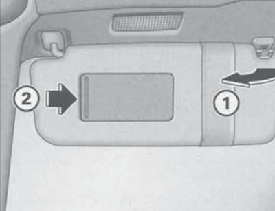
14.14. Driver's sun visor.
The ceiling console, depending on the configuration, combines the lamps and their switches (see below), the control switch for the upper hatch cover (see Section 5), microphone of the hands-free device and voice control system (see Section 20), emergency call button and passenger airbag deactivation key (see Section 9).
The interior lighting is controlled by a switch (And in the illustration 14.15), located in the overhead console, as well as in the housing of the rear individual lamps. To turn on/off the interior lighting, set this switch to the "I" or "0" position, respectively. If you set the switch to an intermediate position, the lighting will turn on when you unlock the car or open the doors, as well as after turning off the ignition; the lighting will be switched off when the car is locked and also approximately 30 seconds after the doors are closed. The keys are used to switch on and off individual interior lights (In the illustration 14.15) in the overhead console and similar buttons in the rear interior light. The interior light switches off automatically if the door remains open for more than 10 minutes.
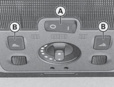
14.15. Light switches in the overhead console. A - Main interior light switch; B - Switches for individual lighting fixtures.
When the ignition is turned on, the door handle lighting is automatically switched on, and when the parking lights are turned on, the center console lighting is switched on (the light is located above the windshield).
The emergency call button, located under the cover with the inscription "SOS", allows you to call the technical assistance of Audi. When you press this button, important information about the location and identification of the car is sent to the central control panel of the technical assistance of Audi. In addition, an emergency call is made by automatic operators when the airbags are deployed.
Note: Do not make an emergency call without proper reasons, as this may result in charges for a false call.
Universal remote control (HomeLink device)
Caution: During programming and each time when remotely controlling the programmed device, it is necessary to ensure that there are no people, animals or foreign objects within the range of the corresponding device.
Universal remote control (with appropriate equipment) located on the sun visor on the driver's side (see illustration 14.16) and is designed to replace several (up to three) separate remote controls, such as those for a garage door or home security system. It recognizes and remembers the signal from the original remote control, after which, instead of using this remote control, you can press the corresponding button on the universal remote control.
Note: Before selling the vehicle, for your own safety, you should erase the settings of the universal remote control (see programming procedure below).
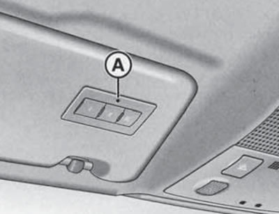
14.16. Universal remote control
If the original remote control has a symbol on its packaging or in its manual
To program your universal remote control, follow these steps:.
1. Turn on the ignition.
2. Press and hold the channel 1 and 3 call buttons simultaneously for about 20 seconds until the indicator starts flashing (And in illustration 14.16), - this clears the memory of all channels; clearing the memory of one channel is not provided.
3. Press one of the call buttons and wait until the indicator starts flashing. After this, the 5-minute programming stage begins.
4. Get out of the car, bring the original remote control no more than 30 cm from the left headlight (see illustration 14.17) and press the power button on it. When all the direction indicators flash three times, the programming is successfully completed.
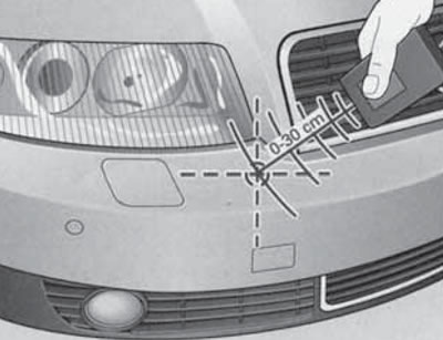
14.17. Location of the transceiver.
5. If the direction indicators do not flash after 15 seconds, repeat the procedure by changing the distance between the remote control and the bumper. The distance is determined by the device that is assigned to the universal remote control.
6. If the 5-minute programming interval has expired, the direction indicators flash once. In this case, repeat the procedure from point 3.
7. To program the remaining channels, repeat the procedure starting from step 3.
To use a programmed channel on the universal remote control, press the corresponding call button with the ignition on.
If the programmed channel does not work, make sure that the original remote control does not use alternative coding. If the indicator flashes rapidly for 2 seconds and then remains lit while holding the corresponding call button, this means that an attempt was made to program a remote control with alternative coding. To program a channel to such a remote control, refer to the instruction manual for that remote control, or try the following programming method.
1. Park the vehicle within range of the remote control.
2. Find the button on the receiver of the controlled device (it is usually located on the electric motor), press it and within 30 seconds press the button on the universal remote control that has already been programmed to this device.
3. Press the button on the universal remote control that the device was already programmed to again - it should work. For some devices, you may need to press the button on the universal remote control a third time.
Equipment of the luggage compartment
Note: Additional information on cargo transportation is provided in Section 25. A description of how to fold down the rear seat back and use the hatch with a cover for transporting long items is provided in Section 10.
The trunk lid of Sedan models contains a warning triangle (see figure 3 Introduction).
An on-board tool kit is stored under the luggage compartment floor (see figure 4 Introduction), spare tire or tire repair kit.
The luggage compartment lighting turns on and off automatically when the luggage compartment is opened or closed. If the luggage compartment is left open for more than 10 minutes, the lighting automatically turns off to prevent the battery from discharging.
To secure the load, you can use a luggage net or slings secured to the rigging hooks (see illustration 14.18).
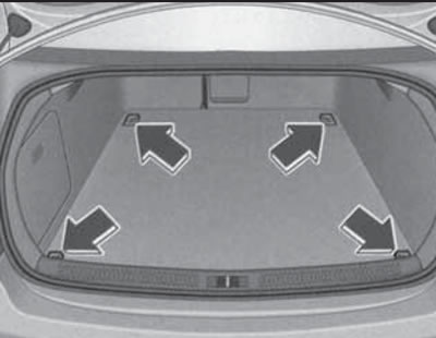
14.18. Rigging loops in the luggage compartment
When using the branded laying net, its middle loops can be secured to the upper hooks (see illustration 14.19). These hooks can also be used for hanging bags, packages, etc. weighing no more than 5 kg.
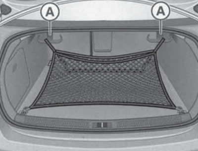
14.19. Hooks for attaching the laying net or bags.
A protective covering should be used for transporting dirty items (From the illustration 14.20). To unfold it, pull the key (A).
Note: Position (B) in the illustration indicates the trunk lid release button. The protective cover can also be placed on the folded down rear seat back.
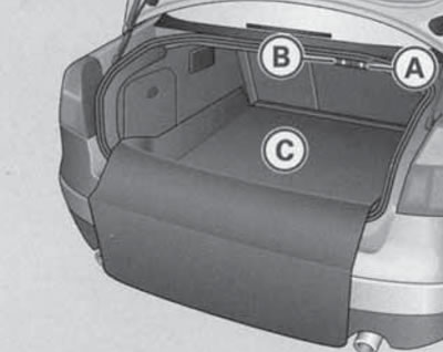
14.20. Straightened protective coating.
In the left side niche of the luggage compartment there is a device for reading the navigation system discs (see illustration 14.21).
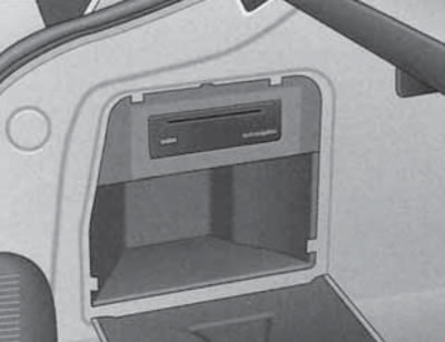
14.21. Navigation disc reading device.
There is a power socket on the right side of the luggage compartment trim (see illustration 14.10), emergency release handle for the fuel filler flap (see illustration 4.1).
The luggage compartment of the station wagon models can be closed with a curtain, pulled out by the handle and secured in the latches.
Note: Do not place heavy or hard objects on the cover, as they may injure passengers during sudden braking or maneuvering. To roll up the luggage compartment cover, release it from the clips and, holding it with your hand, let it retract into the body.
A dividing net, purchased separately, is used to isolate the luggage compartment from the passenger compartment.
(The original source of the article can be found on the website AUDIMANUAL.RU)