
Gear Shift Lever (Type II)
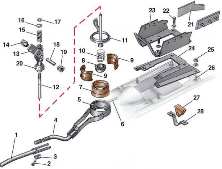
- 1 - front jet thrust;
- 2 - bolt;
- 3 - mounting sleeve;
- 4 - rear jet thrust;
- 5 - hinge housing;
- 6 - support pin;
- 7 - rubber collar;
- 8 - lower hemisphere;
- 9 - insert;
- 10 - spring;
- 11 - metal ring;
- 12 - gear shift lever;
- 13 - hemisphere fork;
- 14, 19 - plates;
- 15 - spring;
- 16 - washer;
- 17 - retaining ring;
- 18 - bushing;
- 20 - upper hemisphere;
- 21 - thrust pad;
- 22 - bolt;
- 23 - bracket;
- 24 - support;
- 25 - nut;
- 26 - hairpin;
- 27 - rubber support;
- 28 - bracket
Gear shift rod (type II)
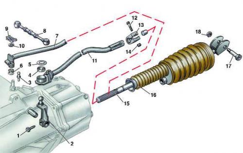
- 1 - bolt;
- 2 - gear shift lever;
- 3 - ball pin;
- 4 - ball joint insert;
- 5 - washer;
- 6 - bushing;
- 7 - jet thrust;
- 8 - adjustable traction;
- 9 - bracket;
- 10 - washer;
- 11 - Front gear shift rod;
- 12 - bolt;
- 13 - terminal;
- 14 - nut;
- 15 - rear gear shift rod;
- 16 - protective cover;
- 17 - axis;
- 18 - nut
Execution order
1. Disconnect rear rod 15 (see Fig. Gear shift rod (type II)) from gear shift lever 12 (see Fig. Gear shift lever (type II)) by unscrewing nut 18 (see Fig. Gear shift rod (type II)) and removing axle 17.
2. Loosen bolt 2 (see Fig. Gear shift lever (type II)) and disconnect the front 1 torque rod from the rear 4. 3. Unscrew four nuts 25.
4. Remove the gear shift lever assembly.
5. Install the gearshift lever in the reverse order. The front 1 and rear 4 parts of the reaction rod are connected so that the pin 6 protrudes from the rubber support 27 by 17 mm.