
Table of contents: Adjusting the starting clearance of… ↓ Adjusting the opening of the… ↓ Adjusting the opening of the… ↓ Adjusting the accelerator pump ↓ Adjusting engine idle speed ↓ Adjusting CO content without a gas… ↓ Adjusting CO content using a gas… ↓
Adjusting the starting clearance of the air damper
Pull the choke control handle out fully; in this case, the air damper control lever should be at the stop.
Press the trigger rod all the way down.
Measure the starting gap of the air damper with a set of feeler gauges, which should be within 4.6±0.15 mm
If the starting clearance of the air damper does not fit within the specified limits, achieve the required clearance by bending the adjusting fork on which the curved end of the starting device rod rests (see photo).
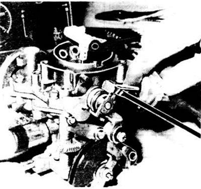
Adjusting the starting gap of the air damper
Adjusting the opening of the throttle valve of the 1st chamber at idle speed of a cold engine
Start and warm up the engine.
Attach the tachometer and remove the air filter.
Pull the choke control handle out fully.
Turn the control lever to completely close the air damper.
Measure the engine crankshaft speed, which should be within 4200±200 rpm.
If necessary, set the required engine mode by moving the throttle control levers of the 1st chamber.
Adjusting the opening of the throttle valve of the 1st chamber in the idle mode of a cold engine
Adjusting the opening of the throttle valve of the 2nd chamber
The position of the throttle valve of the 2nd chamber is adjusted at the manufacturer, but if the adjustment is disturbed, the position can be restored as follows:
- remove the carburetor;
- open the air damper fully;
- set the throttle valve of the 1st chamber to the idle position and fix it;
- unscrew the 2nd chamber throttle valve limit screw so that it moves away from the 2nd chamber throttle valve control lever. Then screw in the limit screw until it touches the lever, then screw in the limit screw another 3/4 turn;
- lock the limit screw with a drop of paint or a special compound;
- put the carburetor back in place;
- adjust the engine idle speed.
Adjusting the accelerator pump
Remove the carburetor.
Place a measuring cup with a funnel under the carburetor.
Slowly open and close the throttle valve of the first chamber ten times, thereby activating the accelerator pump.
Measure the amount of fuel flowing into the measuring cup, which should be within 7.8±1.2 cm³, i.e. 0.78±0.12 cm per cycle.
If there is a deviation from the norm, achieve the required performance of the accelerator pump by changing the position of the pump drive lever stop.
Adjusting engine idle speed
Before adjusting the engine idle speed, perform the following operations:
- make sure the choke control handle is fully depressed;
- warm up the engine. To do this, let the engine run at about 2000 rpm until the thermostat opens. Never warm up the engine at idle, as if the engine runs for several minutes at idle, the carbon monoxide measurements in the exhaust gases will be distorted;
- check the air filter element for cleanliness and replace it with a new one if necessary (when adjusting the engine idle speed, do not remove the air filter);
- check the functionality of the ignition system and the ignition timing;
- check for air leaks, paying particular attention to the connection of the vacuum hoses and the condition of the throttle body gasket;
- make sure there are no significant exhaust leaks in the exhaust tract;
- make sure that powerful current consumers (electric fan of the engine cooling system, headlights, rear window heating element, etc.) turned off.
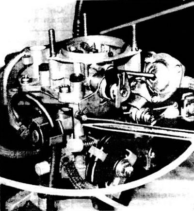
Using the mixture quantity adjusting screw (see photo), set the crankshaft speed within 700-800 rpm.
Precise adjustment of the carbon monoxide (CO) content in exhaust gases is performed only with the help of special equipment. If it is not available, it is permissible to regulate the CO content by acting as indicated below.
Adjusting the idle mixture quantity
Adjusting CO content without a gas analyzer
Set the engine crankshaft speed to 700-800 rpm.
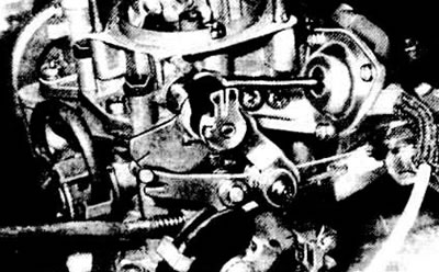
Remove the plug of the mixture quality (composition) adjusting screw (see photo) and, by turning it, achieve the maximum crankshaft speed at idle.

Adjusting the quality (composition) of the idle mixture
Use the mixture quantity adjusting screw to restore the crankshaft speed to 700-800 rpm. Repeat the above operations until the engine runs stably at idle.
Using the mixture quality (composition) adjusting screw, reduce the crankshaft speed by 50 rpm.
Place a plug on the mixture quality (composition) adjustment pint.
Adjusting CO content using a gas analyzer
Set the engine crankshaft speed to 700-800 rpm.
Remove the plug of the mixture quality (composition) adjustment screw and, by turning it, achieve a CO content in the exhaust gases within 0.5-1.5%.
If necessary, restore the crankshaft speed to 700-800 rpm using the mixture quantity adjusting screw.
Repeat these operations until the specified values of crankshaft speed and CO content are obtained.
After adjustment, replace the plug of the mixture quality (composition) adjustment screw.