
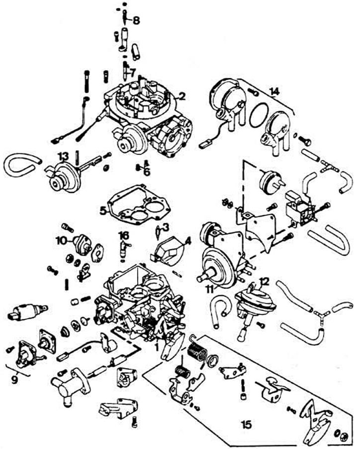
Pierburg 2E2 carburetor parts: 1 - carburetor body; 2 - carburetor cover; 3 - needle valve; 4 - float; 5 - carburetor cover gasket; 6 - main fuel jets; 7 - idle fuel jet; 8 - adjusting screw for idle mixture quality (composition); 9 - accelerator pump; 10 - power mode economizer; 11 - pneumatic drive of the throttle valve of the 1st chamber; 12 - pneumatic drive of the throttle valve of the 2nd chamber; 13 - pneumatic drive of the air damper; 14 - Automatic starting device housing; 15 - Throttle control levers; 16 - accelerator pump nozzle
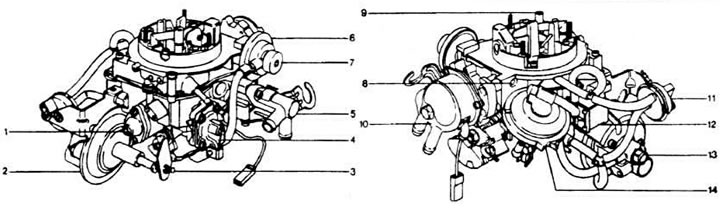
External appearance of the Pierburg 2E2 carburetor: 1 - power mode economizer; 2 - pneumatic drive of the throttle valve of the 1st chamber; 3 - stop screw of the throttle control lever of the 1st chamber; 4 - accelerator pump; 5 - housing of the thermal power element; 6 - pneumatic drive of the air damper; 7 - adjusting screw of the starting gap of the 1st stage of the air damper;8 - adjusting screw of the starting gap of the 2nd stage of the air damper; 9 - mixture quality (composition) adjustment screw; 10 - Automatic starting device cover; 11 - pneumatic valve with thermal time relay; 12 - electromagnetic shut-off valve; 13 - adjusting screw for the output of the pneumatic drive rod of the 1st chamber throttle valve at forced idle; 14 - pneumatic drive of the throttle valve of the 2nd chamber
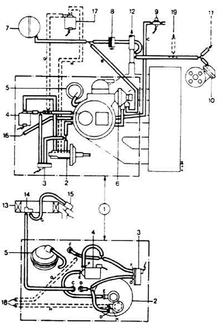
Vacuum hose connection diagram on the Pierburg 2E2 carburetor: 1 - carburetor; 2 - pneumatic drive of the throttle valve of the 1st chamber; 3 - pneumatic valve with thermal time relay; 4 - electromagnetic shut-off valve; 5 - pneumatic drive of the throttle valve of the 2nd chamber; 6 - pneumatic drive of the air damper; 7 - receiver; 8 - check valve; 9 - vacuum switch*; 10 - vacuum regulator of ignition timing of the ignition distributor sensor; 11 - to the econometer; 12 - to the brake booster; 13 - air filter; 14 - thermal pneumatic valve; 15 - pneumatic drive of the air intake flap; 16 - to the thermopneumatic valve; 17 - Cold engine idle speed electromagnetic valve**; 18 - to the cold engine idle speed solenoid valve; 19 - to the air conditioner. The hoses marked with a dotted line are installed on cars with air conditioning. Wire color designation: A - black; B - light green; C - colorless; O - brown; E - yellow; F - blue; G - white; H - pink