
Fuel injection system "KE-III-Jetronic" with knock sensor
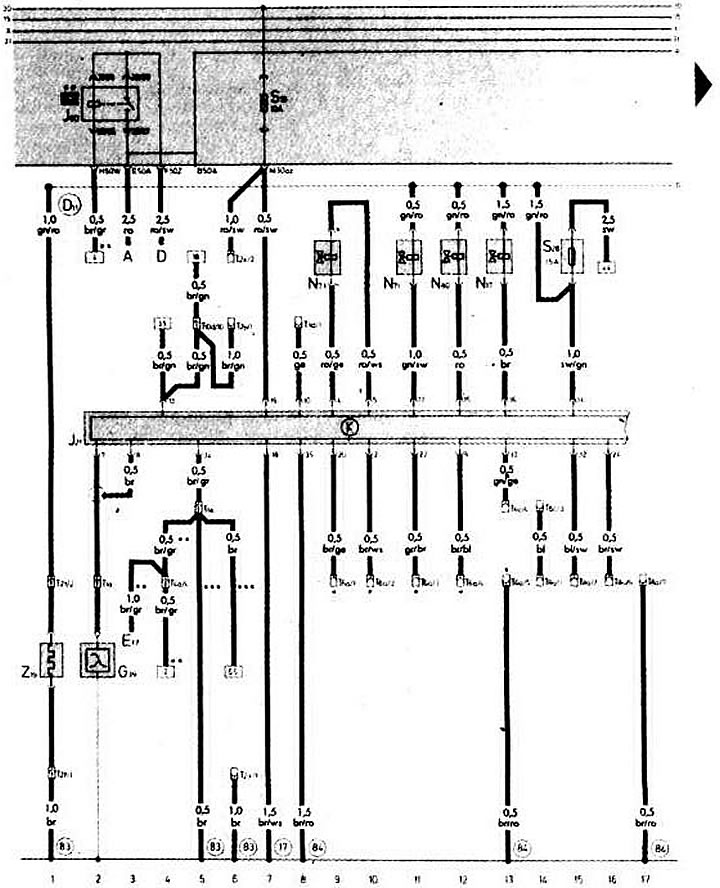
- A - storage battery
- D — ignition switch
- E17 - to the engine start circuit switch and the reversing light switch
- G39 - Oxygen concentration sensor (2341) with heating element (2342)
- J21 — electronic control unit for the injection system
- J60 — automatic transmission relay
- N17 - starting injector (4443)
- N71 - idle speed control valve (4431)
- N73 - pressure regulator (4341)
- N80 — pulse solenoid valve (4343) of the adsorber
- S19 — fuse in the mounting block
- S28 — fuse for electronic fuel injection control unit
- T1a - single-plug connector (in the powertrain compartment, on the left)
- T1e - single-plug connector (black, behind the instrument cluster)
- T2f - 2-pin connector (black, in the powertrain compartment, on the left)
- T2x — 2-plug diagnostic connector (black, behind the instrument cluster)
- T2u - 2-plug connector (brown, behind the instrument cluster)
- T3d - 3-pin connector (black, behind the instrument cluster)
- T4a - 4-pin connector (behind the instrument cluster)
- TBA - 6-pin connector (black, behind the instrument cluster)
- TBS - 6-pin connector (black, behind the instrument cluster)
- T8a - 8-pin coding connector (black, behind the instrument cluster)
- T10d - 10-pin connector (yellow, behind the instrument cluster)
- Z19 — heating element of the oxygen concentration sensor
- (17) - ground connection on the intake manifold
- (83) - connection to ground "-1-" of the right front wire harness
- (84) - connection to ground (engine weight) right front wiring harness
- (D11) - connection to "+" (to contact "15" of the ignition switch) via fuse No.28 in the right front wiring harness
- * — coding connector installed on the vehicle
- ** — only for cars with automatic transmission
- *** — only for vehicles with manual transmission
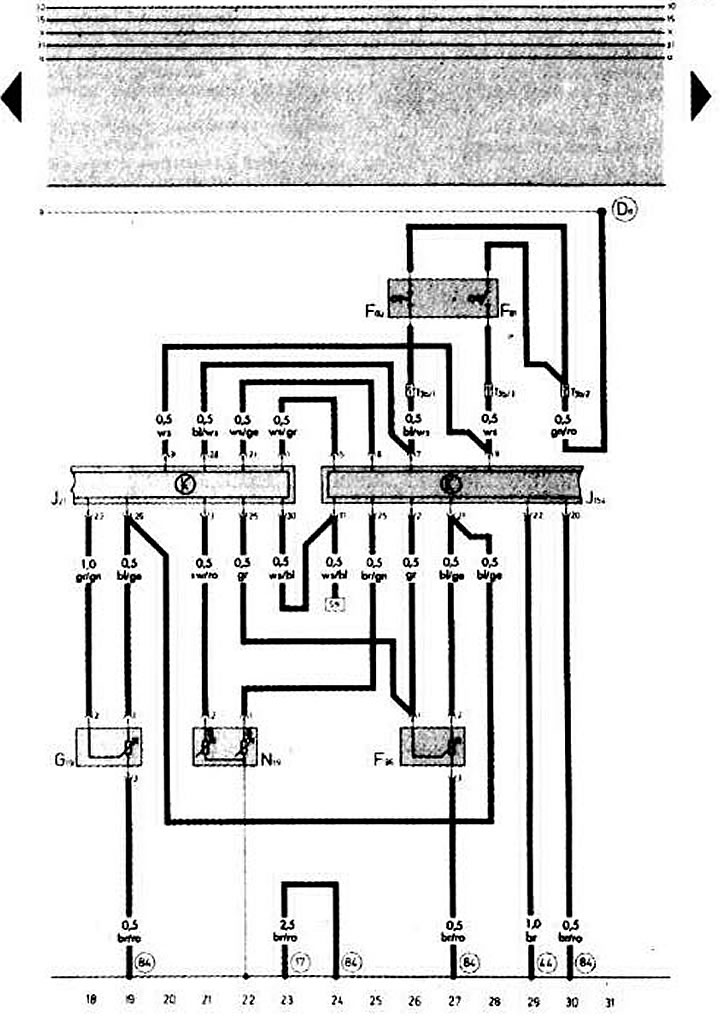
- F60 - Idle switch (2121)
- F81 - Full Load Switch (2123)
- F96 - altitude sensor (2223)
- G19 - Air flow meter potentiometer (2232)
- J21 — electronic control unit for the injection system
- J154 - Electronic control unit for fully electronic ignition system with knock sensor
- N19 - temperature sensor
- T3b - 3-pin connector (black, in the powertrain compartment, on the left)
- (87) - ground connection on the intake manifold
- (44) - ground connection on the front door pillar, bottom left
- (84) - connection to ground (engine weight) right front wiring harness
- (D11) — connection to "+" (to contact "15" of the ignition switch) via fuse No.28 of the right front wiring harness
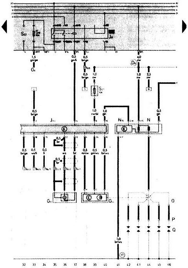
- G6 - fuel pump
- G40 - Hall sensor (2113)
- G61 - Knock Sensor (2142)
- J17 — fuel pump relay (4433)
- L 54 - electronic control unit for a fully electronic ignition system with a knock sensor
- N — ignition coil
- N70 - ignition coil with power amplification output stage
- O — ignition distributor
- P - spark plug tips
- Q — spark plugs
- S13 — fuse in the mounting block
- S22 — fuse in the mounting block
- S27 — Knock sensor control unit fuse
- T3c - 3-pin connector (black, in the powertrain compartment, on the left)
- T8a - 8-pin coding connector (black, behind the instrument cluster)
- T10 - 10-pin connector (blue, behind the instrument cluster)
- (17) - ground connection on the intake manifold
- (D9) — connection to "+" (to contact "15" of the ignition switch) via fuse No.24 of the right front wiring harness
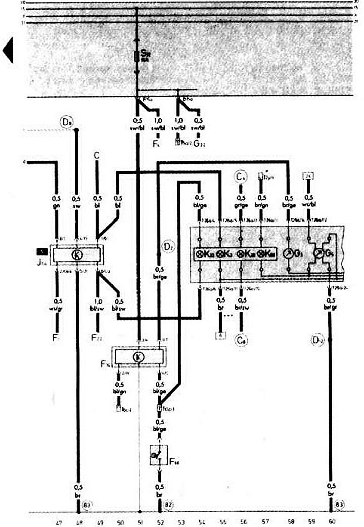
- C - generator
- F1 — oil pressure sensor calibrated to 1.8 kg/cm²
- F4 — reverse light switch
- F22 — oil pressure sensor calibrated to 0.3 kg/cm²
- F66 — Coolant low level indicator switch
- F76 - electronic thermal switch
- G3 - coolant temperature gauge
- G5 - tachometer
- G22 - speedometer sensor
- J114 - Oil pressure warning lamp control unit
- K3 - oil pressure indicator lamp
- K28 - control lamp for emergency overheating and coolant level
- K32 - Brake lining wear warning lamp (PADS)
- K66 - warning lamp for malfunction of fully electronic ignition system
- S12 — fuse in the mounting block
- T2u — 2-plug diagnostic connector (brown, behind the instrument cluster)
- T5a - 5-pin connector (brown, behind the instrument cluster)
- T6c - 6-pin connector (black, behind the instrument cluster)
- T10d - 10-pin connector (yellow, behind the instrument cluster)
- T26a - 26-pin connector (brown color) instrument clusters
- (82) - ground connection "-1-" of the left front wire harness
- (83) - ground connection "-1-" of the right front wire harness
- (C4) — connector of the left front wire harness
- (C8) - Brake pad wear sensor connector in the left front wiring harness
- (D2) - temperature sensor connector in the right front wiring harness
- (D9) — connection to "+" (to contact "15" of the ignition switch) via fuse No.24 of the right front wiring harness
- (D12) - 5-cylinder engine coding connector in the right front wiring harness
- * - only on cars in the "economy" version for the USA
- ** — only for vehicles with manual transmission