Repair Chevrolet Repair Toyota Repair Honda Repair AvtoVAZ Repair Mercedes-Benz Repair BMW Repair Opel
Home  |  Contacts  |  Sitemap  |    
English Русский
Български
Беларускі
Український
Српски
Hrvatski
Română
Polski
Slovenský
Magyar
AudiManual.ru


  • AUDI 80
  • AUDI 100
  • AUDI A3
  • AUDI A4
  • AUDI A6
  • AUDI A8
  • AUDI Q
  • OTHER
  • ARTICLES
C4 (1990-1994) C4 (1990-1994, petrol) C3 (1982-1990) C3 (1982-1990, petrol) C3 (1982-1990, diesel)

Instruments — removal, testing and installation (Audi 100 C3)

  • Home
  • Audi 100
  • C3 (1982-1990, diesel)
  • Electrical equipment
  • Equipment and devices
  • Instruments — removal, testing and installation
            0
1. Remove the instrument panel as described in Chapter 8.

2. Remove the appropriate device, component or printed circuit board, referring to Figures 12.10, 12.11 and 12.12.

2. Remove the appropriate device, component or printed circuit board, referring to Figures 12.10,…


2. Remove the appropriate device, component or printed circuit board, referring to Figures 12.10,…


2. Remove the appropriate device, component or printed circuit board, referring to Figures 12.10,…


3. Many devices require the use of an Audi tester to check, but the following can be performed without the use of special equipment.


4. To check the voltage stabilizer, connect the device wiring and restore the connection of the negative battery terminal.

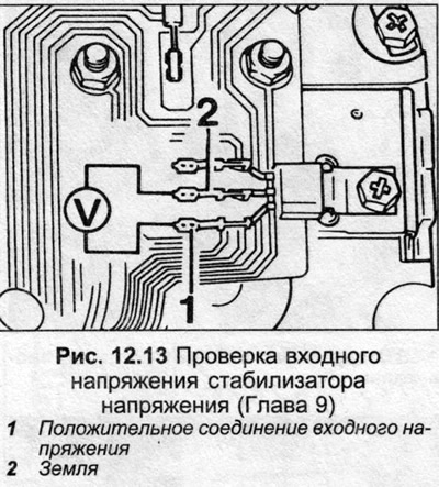
5. Connect a voltmeter between the positive connection of the voltage regulator and ground (fig. 12.13) (photo). Turn on the ignition, the voltmeter should show approximately the battery voltage. If not, check for damage to the wiring that feeds the stabilizer.

5. Connect a voltmeter between the positive connection of the voltage regulator and ground (fig.…


5. Connect a voltmeter between the positive connection of the voltage regulator and ground (fig.…


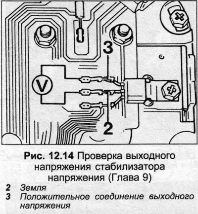
6. Check the output voltage of the stabilizer by connecting a voltmeter between connection 3 (positive output) and 1 (ground), as shown in Fig. 12.14. With the ignition on, the voltage should be 9.75-10.25 volts. If not, replace the voltage stabilizer. Turn off the ignition after completing the check.

6. Check the output voltage of the stabilizer by connecting a voltmeter between connection 3…


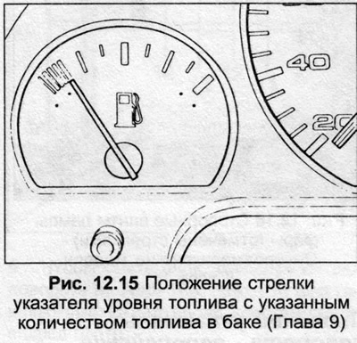
7. The accuracy of the fuel gauge can be checked as follows: Remove all fuel from the tank, then add exactly 12.0 liters of fuel.


8. Turn on the ignition, wait two minutes for the meter readings to stabilize. After this, the pointer should align with the upper edge of the red reserve zone. If necessary, turn the adjusting screw under the pointer to correct the readings.

9. The instrument panel is assembled in the reverse order.

9. The instrument panel is assembled in the reverse order.


(The text is based on materials from the website: audimanual)
The article was checked by auto expert Nikita Rudakov
This article is available at russian, bulgarian, belarusian, ukrainian, serbian, croatian, romanian, polish, slovak, hungarian

Share information:
Previous articles
Audi 100 C3: Equipment and devices
Next articles

Instrument panel — removal and installation
Interior Light Switches — Removal and Installation
Switches on the central console and on the panel — removal and…
Combination switch — removal and installation
Speedometer Drive Cable — Removal and Installation
Headlights and headlight bulbs — removal and installation
Headlights — adjustment
Lamps and lamp units — removal and installation


Similar articles on other Audi car models:
Removal, installation, testing of cold start valve (K-,… Audi 80 B3 (1986-1991)
Removal and installation the lower engine compartment cover Audi A3 Type 8L (1996-2003)
Installation and removal of the cylinder head Audi A4 B5 (1994-2001, petrol)
Removal and installation of cylinder head of petrol engines V6… Audi A6 C5 (1997-2004)
Removal and installation the engine Audi A8 D2 (1994-2002)
Turbocharger — removal and installation Audi Q5 Type 8R (2008-2017)
Removal and installation the engine Audi A2 (1999-2005)
Link to this page in different formats


Visitor comments

No comments yet


How much will 18 + 40 =


100(C4, 1990-1994) 
  • General information
  • User manual
  • Power unit
  • Engine repair
  • Ignition system
  • Fuel system (gasoline)
  • Fuel system (diesel)
  • Lubrication system
  • Cooling system
  • Exhaust system
  • Transmission
  • Clutch
  • Car gearbox
  • Drive shafts
  • Chassis
  • Car suspension
  • Steering
  • Wheels and tires
  • Brake system
  • Body
  • Ventilation and heating
  • Body repair
  • Electrical equipment
  • Power devices
  • Lighting and appliances
  • Electrical circuits
 
100(C4, 1990-1994, petrol) 
  • General information
  • Operation and maintenance
  • Power unit
  • Engine repair
  • Exhaust system
  • Cooling system
  • Supply system
  • Air filter
  • Mono-Motronic injection system
  • Digifant injection system
  • KE-III-Jetronic and KE-Motronic
  • MPI and MPFI injection system
  • Transmission
  • Clutch
  • Car gearbox
  • Chassis
  • Suspension and steering
  • Brake system
  • Wheels and tires
  • Body
  • Exterior
  • Interior
  • Electrical equipment
  • Fuses and relays
  • Power devices
  • Ignition system
  • Lighting and signaling
  • Equipment and devices
  • Electrical circuits
 
100(C3, 1982-1990) 
  • General information
  • User manual
  • Maintenance
  • Specifications
  • Power unit
  • Engines 4-cylinder
  • Engines 5-cylinder
  • Diesel engine
  • Cooling system
  • Power system (carburetor)
  • Power system (injector)
  • Fuel system (diesel)
  • Transistor ignition system
  • Electronic ignition system
  • Transmission
  • Clutch
  • 4 speed gearbox 014
  • 5 speed gearbox 013 and 093
  • 5 speed gearbox 016 and 012
  • Shift mechanism KP 016
  • Automatic transmission
  • Front wheel drive
  • Chassis
  • Front suspension
  • Rear suspension
  • Steering
  • Brake system
  • Body
  • Body elements
  • Electrical equipment
  • Lighting and appliances
  • Power devices
  • Electrical circuits
 
100(C3, 1982-1990, petrol) 
  • General information
  • Maintenance and operation
  • 4 cylinder engine
  • Engine repair
  • Cooling and lubrication system
  • Supply system
  • Ignition system
  • 5 cylinder engine
  • Engine repair
  • Cooling and lubrication system
  • Supply system
  • Ignition system
  • Transmission
  • Clutch and drive shafts
  • 4 speed gearbox 014
  • 5 speed gearbox 013 and 093
  • 5 speed gearbox 016 and 012
  • Automatic gearbox
  • Chassis
  • Steering
  • Front suspension
  • Rear suspension
  • Brake system
  • Body
  • Body elements
  • Doors, locks and windows
  • Body repair
  • Electrical equipment
  • Equipment and devices
  • Power devices
  • Electrical circuits
 
100(C3, 1982-1990, diesel) 
  • General information
  • User manual
  • Maintenance
  • Troubleshooting
  • Power unit
  • Engine in a car
  • Engine removed
  • Cooling system
  • Fuel system
  • Exhaust system
  • Starting and charging
  • Preheating
  • Transmission
  • Clutch
  • Mechanical gearbox
  • Automatic gearbox
  • Drive shafts
  • Chassis
  • Brake system
  • Suspension
  • Steering
  • Body
  • Exterior
  • Interior
  • Electrical equipment
  • Equipment and devices
  • Electrical circuits
 
AudiManual.ru © 2017-2026 · Mobile version · Feedback · Sitemap: EN BG BY UA RS HR RO PL SK HU · Site search · News and articles
80 B2 · 80 B3 petrol · 80 B3 · 80 B4 · 100 C3 diesel · 100 C3 petrol · 100 C3 · 100 C4 petrol · 100 C4 · A3 Type 8L · A4 B5 petrol · A4 B5 · A4 B6 petrol · A4 B6 · A4 B7 · A4 B8 · A6 C4 · A6 C5 · A6 C5 Allroad · A8 D2 · Q5 Type 8R · Q7 Typ 4L · Audi A2 ·
This site uses cookies 🍪. Click the button to accept this fact.