
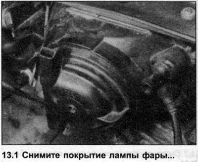
1. From inside the engine compartment, remove the cover on the back of the headlight by turning it counterclockwise (photo).
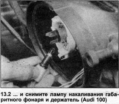
2. Remove the parking light bulb socket from the headlight, then push, twist and remove the bulb (photo).
Front Side Marker Lights - North American Models
3. From inside the engine compartment, remove the rubber boot and bulb holder from the side marker lights.
4. Push, twist and remove the bulb.
Front Direction Indicator - European Models
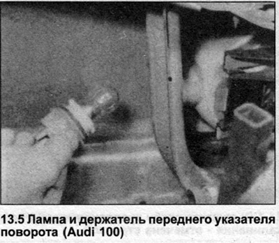
5. On Audi 100 models, turn the bulb holder on the back of the unit counterclockwise and remove it (photo). To replace, push and twist the bulb.
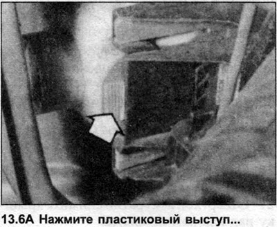
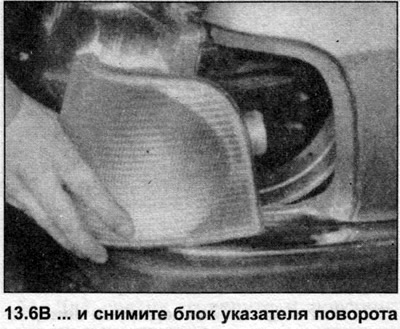
6. To remove the turn signal lamp unit on the Audi 100, press the plastic tab on the side and pull the unit forward (photo).
7. On Audi 200 models, to replace the bulb, remove the two screws on the front of the lens and remove the lens. Push, twist and remove the bulb.
8. To remove the lamp unit, disconnect the electrical wiring, unscrew the mounting screws on the rear part and remove the unit from the bumper.
Additional Motion Lamps - North American Models
9. From inside the engine compartment, release the cover retaining clip, rotate the clip upward and remove the cover.
10. Disconnect the wiring from the bulb, remove the retaining clip and remove the bulb.
Front Fog Light - European Models
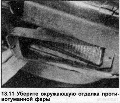
11. Remove the surrounding trim (where is it used) in front of the lamp unit (photo).
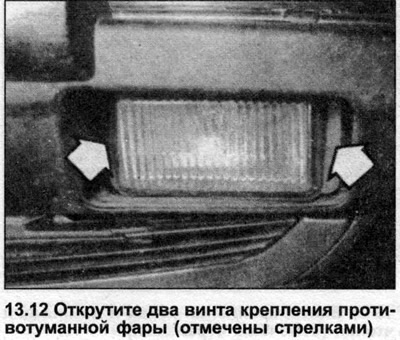
12. Unscrew the two mounting screws and pull out the lamp unit (photo).
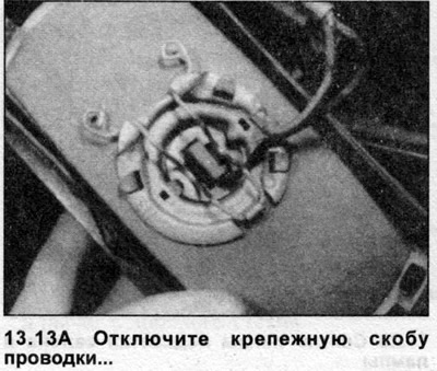
13. Disconnect the wiring retaining clip on the back of the bulb (photo), then lift the bulb holder out of the bulb assembly (photo).
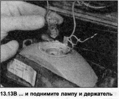
14. Remove the incandescent bulb by pulling it out of the holder.
Rear light unit
15. In the luggage compartment, unscrew the two knurled nuts and remove the cover on the rear of the unit.
16. Press the latches on each side of the lamp plate, remove the plate from the unit (photo).
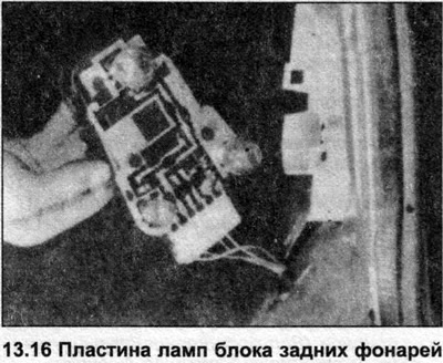
17. To remove, push and turn the bulb (photo).

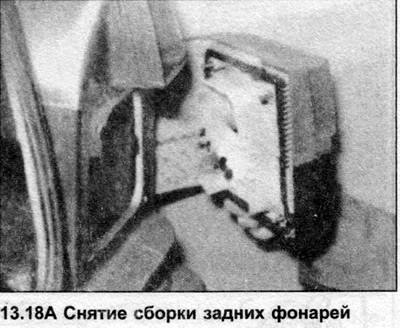
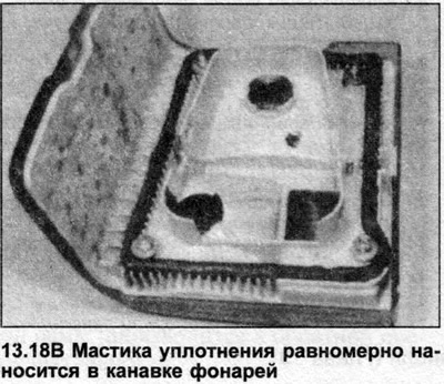
18. To remove the lamp unit, unscrew the four lock nuts, remove the washers, then carefully remove the unit from the body (photo). When installing, check that the sealant mastic is evenly applied around the groove in the lamp unit (photo).
Lamp in trunk lid/rear door
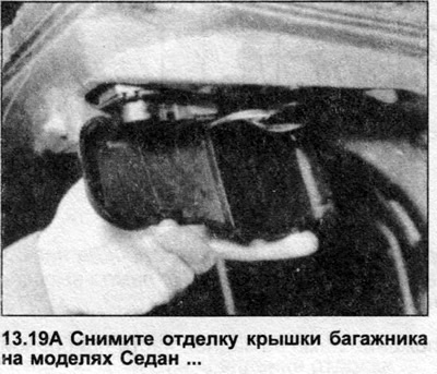
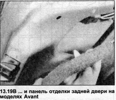
19. Open the trunk/tailgate and use a screwdriver to carefully remove the trim panel on the back of the light unit (photo).
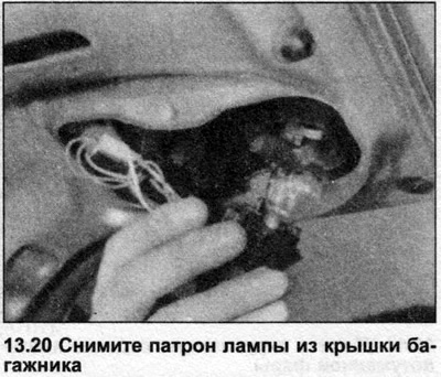
20. Turn the bulb holder counterclockwise and remove it from the light unit (photo).
21. To remove, press and turn the bulb.
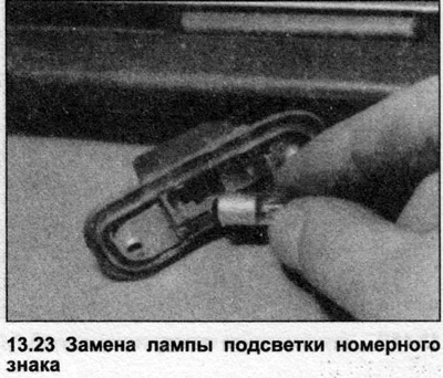
Number plate/license plate illumination
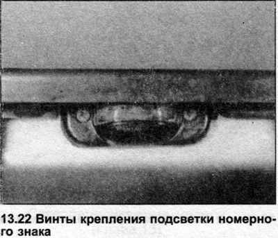
22. Open the trunk/tailgate and remove the two screws securing the lens cover (photo).
23. Remove the lens and bulb assembly, then remove the bulb by pushing and turning it (photo).
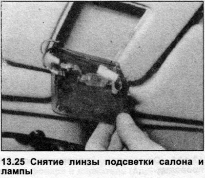
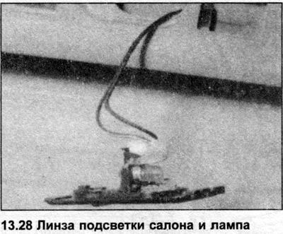
Interior lighting
24. Gently press inward the clip on the edge of the lens on the side opposite the switch.
25. Remove the lens, remove the lamp from the contacts (photo).
Reading lamp
26. Lower the handle, unscrew the two screws above the handle hinges (photo).
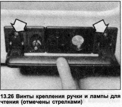
27. Using a screwdriver, carefully remove the cover over the cover hook.
28. Unscrew the cover hook screw and remove the incandescent lamp holder (photo).
29. To remove, press and turn the bulb.
Trunk light lamp
30. Using a screwdriver, carefully remove the lamp holder and lens.
31. Remove the incandescent lamp from the contacts.
Instrument panel lights
32. Remove the instrument panel as described in Chapter 8.
33. Turn the bulb holder 90° and remove it from the instrument panel (photo).
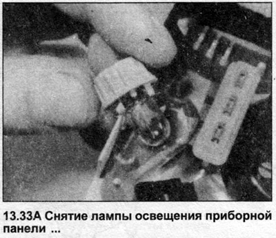
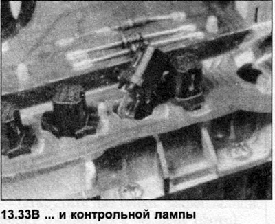
34. Pull out the wedge lamp.
Glove compartment lamp
35. Open the glove compartment, remove the switch/lamp holder.
36. To remove, push and twist the bulb.
All lamp units
37. Installation is carried out in reverse order.
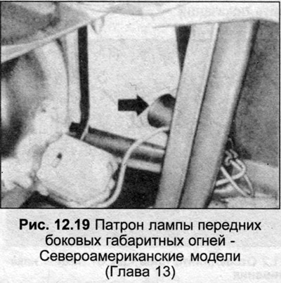
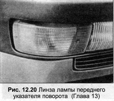
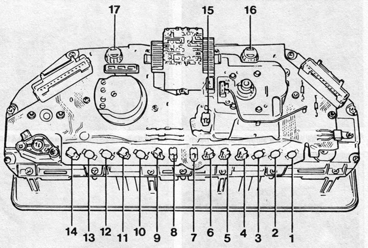
Fig. 12.21 Location of lamps on the rear of the instrument panel (Chapter 13)
1 — Anti-lock braking system indicator lamp (uK only)
2 — Seat belt indicator light (uK only)
3 — Low coolant temperature indicator lamp (uK only)
4 — Handbrake indicator light
5 — Generator load indicator lamp
6 — Oil pressure indicator light (United Kingdom)/OXS systems (North America)
7 — Trailer direction indicator light (United Kingdom)/left turn signal (North America)
8 — Hazard warning light (United Kingdom)/right turn signal (North America)
9 — High beam indicator lamp
10 — Rear fog light indicator lamp
11 — Rear window heating indicator lamp
12 — Front seat heating indicator lamp
13 — Direction indicator lamp (uK only)
14 — Seat belt indicator light (north America only)
15 - Digital clock lighting
16 - Right instrument panel lighting
17 - Left instrument panel lighting
Note: Additionally for some UK models, not shown in illustration - the brake warning light and high coolant temperature warning light are located in the centre of the dash.