
Hydraulic module
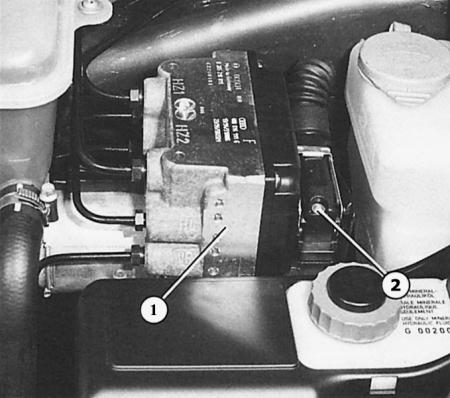
The hydraulic module (1) of the anti-lock system is located at the front left in the engine compartment. It is connected via a central connector (2) to the control unit under the rear seat.
It is located at the front left in the engine compartment: the module is installed between the brake lines of the master cylinder and the brake pipes leading to the wheel brakes. In accordance with the orders of the electronic control unit, the pressure in the brake system circuits is either kept constant, or reduced, or increased again. But the pressure cannot be higher than that which you create by pressing the brake pedal. The pressure is regulated by four rapidly switching electromagnetic valves - one for each wheel.
If the electromagnetic valves are de-energized, the pressure increases. If the maximum current is supplied, the pressure decreases; with an average current, the pressure remains at one level. The pressure release phase is of particular interest: since it is impossible to simply release the brake fluid somewhere to reduce the pressure (to do this, the brake pedal would have to be fully depressed), coming here from the main brake cylinder, the brake fluid is pumped back to the main brake cylinder by a powerful return pump. You notice this by the behavior of the brake pedal, which begins to pulsate slightly when the return pump is working, i.e. ABS starts working. If you listen carefully, you can hear the noise of the pump working. Special dampers in the hydraulic module suppress this noise a little.
Speed sensors
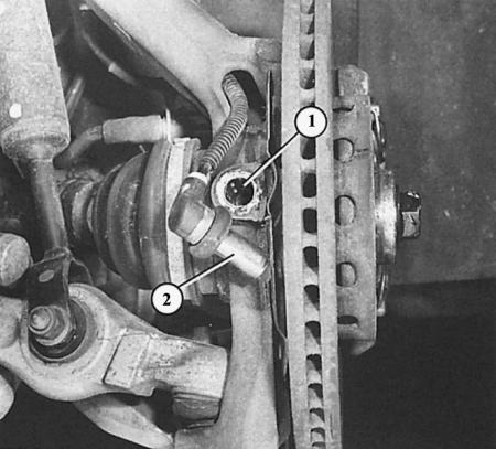
Such speed sensors (2) are installed on all four wheels in the holes (1) of the axle suspension. Behind them, in accordance with the speed of rotation of the wheels, toothed elastic washers rotate.
Only four sensors record the rotation speed of each wheel and transmit this information to the electronic control unit. Based on this, the electronic control unit regulates the operation of the hydraulic module.
The speed sensors themselves consist of a magnetic core and a coil and are mounted a short distance from a toothed disk – the rotor. The rotor – its name speaks for itself – rotates together with the wheel and makes the toothed protrusions around its perimeter rotate past the sensor faster or slower depending on the speed. Each tooth passing under the sensor induces a short voltage rise in the sensor. In this way, an alternating voltage is created in the sensor, which changes its frequency in accordance with the speed of the wheel. The resulting signal is processed by the electronic control unit as information about the number of revolutions of the wheel.
In the Audi A4, the rotors are located on the two or four (quattro) driven wheels on the outer joint of the drive shaft and on the hubs of the non-driven rear wheels.
Electronic control unit
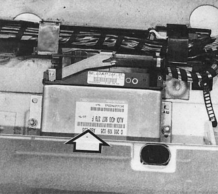
The combined control unit (arrow) for the anti-lock braking system and the electronic differential lock is located approximately in the middle of the vehicle under the rear seat.
The electronic control unit is located under the rear seat and processes information coming from the speed sensors.
At the same time, it controls the hydraulic module so that the wheels do not lock. In addition to signal processing and the subsequent logic part, the control unit also has a locking circuit. With this, the device can check itself, recognize malfunctions and monitor the operating voltage. If malfunctions are detected, it switches off the ABS and the indicator light in the combined instrument lights up.
Content source: the specified website audimanual.ru