
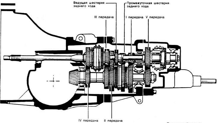
Longitudinal section of gearbox type 013
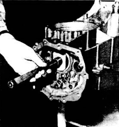
Remove the outer ring of the secondary shaft front tapered roller bearing, having first removed the cylindrical pin on the 013 type gearbox and unscrewed the hexagon socket head bolt on the 093 type gearbox. If necessary, press in a new ring.
Pressing in the outer ring of the secondary shaft rear bearing
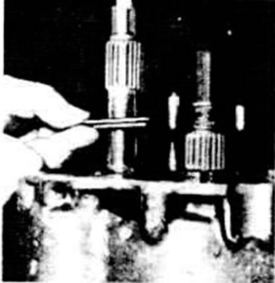
Removal the locking pin of the inner ring of the front bearing of the secondary shaft of the gearbox type 013
Set the shift fork rod locks and retainers to the correct position.
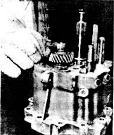
Install the secondary shaft with the 1st and 2nd gear shift fork into the gearbox housing.
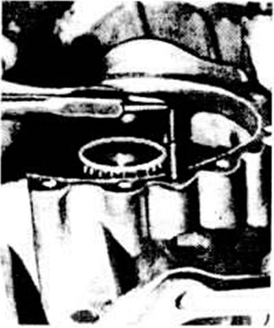
Install the reverse idler gear onto the axle, then press the axle into place.
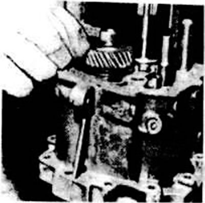
Install the primary shaft with the shift fork for III and IV gears into the crankcase.
Move the 1st and 2nd gear shift fork rods, as well as the 5th gear and reverse gear forks, to the neutral position.
Install the fork rod of the III and IV gears together with the retainer pre-lubricated with consistent grease, insert the spring pin into the fork, holding the rod with a hammer.
Press on the first inner race of the secondary shaft rear double-row tapered roller bearing.
Pressing on the inner ring of the secondary shaft rear bearing
Install the thrust washer on the primary shaft with the protruding part towards the gearbox housing. Heat to a temperature of about 120°C and install the inner ring of the 5th gear bearing in place until it stops, using a 30-23 mandrel if necessary. Hold the primary shaft in place.
Installing the V-gear thrust washer on the primary shaft
Heat to a temperature of about 120°C and install the V gear on the secondary shaft, pushing it all the way, using a 30-100 mandrel if necessary. Hold the secondary shaft while doing this.
Installing the V gear on the secondary shaft
Place the 5th gear pinion on the primary shaft together with the hub and the synchronizer sliding sleeve, the needle bearing and the 5th gear engagement fork. Secure the fork to the rod with a spring pin, holding the rod with a hammer.
Install the 5th gear synchronizer locking ring.
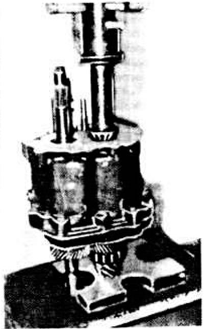
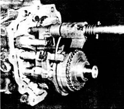
Installing the V gear synchronizer
Heat to about 120°C and install the V-gear synchronizer assembly. If necessary, use the 30-23 mandrel to push it onto the primary shaft until it stops. Fix the position of the primary shaft.
Install a new sealing gasket and attach the gearbox housing with the primary and secondary shafts installed to the clutch housing. Replace the mounting studs and tighten the housing mounting bolts to a torque of 2.5 kgf·m.
Engage any gear and lock the input shaft with lock 2946/1.
Tighten the nut on the rear end of the secondary shaft to a torque of 10.0 kgf·m and lock it.
Move the fork rod of the 1st and 2nd gears forward and engage 3rd gear by pulling the fork rod back.
Install the gear selector shaft:
- place the ends of the spring on the fork rod of the III and IV gears;
- move the gear selection rod lever onto the fork rod of III and IV gears;
- align the gear selector shaft and insert it into the guide sleeve.
Set the fork rods to neutral position.
Gearbox assembly position of gear selector rod
Align the holes in the leash and fork stem of the first and second gears and insert the spring pin
Install a new sealing gasket and reinstall the gearbox housing rear cover using an M10 threaded rod.
Tighten the hex bolt at the rear end of the input shaft to a torque of 4.5 kgf·m.
Tighten the rear crankcase cover mounting bolts to a torque of 2.5 kgf·m, having first applied a special adhesive such as VW D3 to their threads.
[The original article is available on the online resource «AUDIMANUAL»]