Repair Chevrolet Repair Toyota Repair Honda Repair AvtoVAZ Repair Mercedes-Benz Repair BMW Repair Opel
Home  |  Contacts  |  Sitemap  |    
English Русский
Български
Беларускі
Український
Српски
Hrvatski
Română
Polski
Slovenský
Magyar
AudiManual.ru


  • AUDI 80
  • AUDI 100
  • AUDI A3
  • AUDI A4
  • AUDI A6
  • AUDI A8
  • AUDI Q
  • OTHER
  • ARTICLES
C4 (1990-1994) C4 (1990-1994, petrol) C3 (1982-1990) C3 (1982-1990, petrol) C3 (1982-1990, diesel)

Disassembly and assembly of the primary shaft (Audi 100 C3)

  • Home
  • Audi 100
  • C3 (1982-1990, petrol)
  • Transmission
  • 5 speed gearbox 013 and 093
  • Disassembly and assembly of the primary shaft
            0
Table of contents: Disassembly ↓ Assembly ↓

Disassembly


Remove the 4th gear retaining ring.

Remove the thrust washer and the fourth gear with the needle bearing.

Place the primary shaft with the 3rd gear pinion on a press and press off the 3rd gear pinion, the synchronizer sliding sleeve and the hub with the synchronizer locking rings.

When connecting the hub with the sliding sleeve of the synchronizer of the third and fourth gears,…

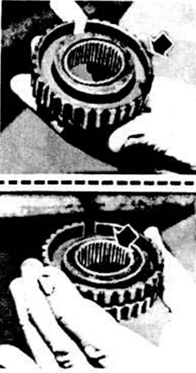
When connecting the hub with the sliding sleeve of the synchronizer of the third and fourth gears, direct the groove on the outer rim of the hub towards the fourth gear pinion, and the beveled edge of the inner splines of the hub towards the third gear pinion


Check the wear of the synchronizer locking wheels. To do this, press the locking rings against the gear synchronizer cones and use a feeler gauge to measure the axial clearance between the end of the locking ring and the end of the gear synchronizer ring gear, which should be at least 0.5 mm. If the clearance is smaller, replace the synchronizer locking rings.

Measuring the axial clearance «a» between the end face of the locking ring and the end face of the…

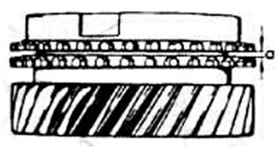
Measuring the axial clearance "a" between the end face of the locking ring and the end face of the synchronizer gear ring


Press the inner race of the rear bearing using a press.

Assembly


Connect the sliding sleeve to the synchronizer hub of the third and fourth gears, directing the beveled edge of the internal splines of the hub towards the third gear pinion, and the installation groove on the outer rim of the hub towards the fourth gear pinion (see photo).

Slide the sliding sleeve onto the synchronizer locking rings, aligning the cracker grooves on the rings and the hub. Install the crackers and springs by arranging the spring connectors at 120°. The curved ends of the springs must be inserted into the cracker recesses.

Install the 3rd gear pinion together with the needle bearing.

Press the synchronizer of III and IV gears onto the shaft.

Install the 4th gear pinion together with the needle bearing.

Measure the axial runout of the fourth gear pinion and install the appropriate thrust washer so that the clearance is within 0.10-0.40 mm.

Measuring the axial clearance of the fourth gear of the primary shaft to determine the thickness of…

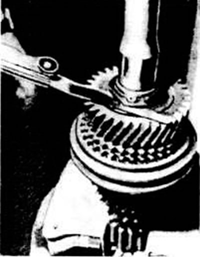
Measuring the axial clearance of the fourth gear of the primary shaft to determine the thickness of the thrust washer


Install the rear bearing inner race using a drift.
The article was checked by auto expert Maxim Rybakov
This article is available at russian, bulgarian, belarusian, ukrainian, serbian, croatian, romanian, polish, slovak, hungarian

Share information:
Previous articles
Audi 100 C3: 5 speed gearbox 013 and 093
Next articles

Disassembling the gearbox
Removal and installation the gearbox
Details of five-speed gearbox types 013 and 093
Tightening torques for main threaded connections
Disassembly and assembly of the secondary shaft
Gearbox assembly
Disassembling and assembling the differential
Distance between the end face of the main gear pinion and the…


Similar articles on other Audi car models:
Disassembly and assembly of the primary shaft Audi 80 B2 (1979-1986)
Clutch and Drive Shaft Specifications Audi A3 Type 8L (1996-2003)
Cylinder head — disassembly, cleaning, inspection and assembly Audi A4 B5 (1994-2001)
Disassembly and assembly of the drive shaft Audi A6 C5 (1997-2004)
Disassembly and assembly of the shock absorber strut Audi A8 D2 (1994-2002)
Disassembly and assembly of the engine Audi Q5 Type 8R (2008-2017)
Disassembly and assembly of the gearshift mechanism drive Audi A2 (1999-2005)
Link to this page in different formats


Visitor comments

No comments yet


How much will 38 + 39 =


100(C4, 1990-1994) 
  • General information
  • User manual
  • Power unit
  • Engine repair
  • Ignition system
  • Fuel system (gasoline)
  • Fuel system (diesel)
  • Lubrication system
  • Cooling system
  • Exhaust system
  • Transmission
  • Clutch
  • Car gearbox
  • Drive shafts
  • Chassis
  • Car suspension
  • Steering
  • Wheels and tires
  • Brake system
  • Body
  • Ventilation and heating
  • Body repair
  • Electrical equipment
  • Power devices
  • Lighting and appliances
  • Electrical circuits
 
100(C4, 1990-1994, petrol) 
  • General information
  • Operation and maintenance
  • Power unit
  • Engine repair
  • Exhaust system
  • Cooling system
  • Supply system
  • Air filter
  • Mono-Motronic injection system
  • Digifant injection system
  • KE-III-Jetronic and KE-Motronic
  • MPI and MPFI injection system
  • Transmission
  • Clutch
  • Car gearbox
  • Chassis
  • Suspension and steering
  • Brake system
  • Wheels and tires
  • Body
  • Exterior
  • Interior
  • Electrical equipment
  • Fuses and relays
  • Power devices
  • Ignition system
  • Lighting and signaling
  • Equipment and devices
  • Electrical circuits
 
100(C3, 1982-1990) 
  • General information
  • User manual
  • Maintenance
  • Specifications
  • Power unit
  • Engines 4-cylinder
  • Engines 5-cylinder
  • Diesel engine
  • Cooling system
  • Power system (carburetor)
  • Power system (injector)
  • Fuel system (diesel)
  • Transistor ignition system
  • Electronic ignition system
  • Transmission
  • Clutch
  • 4 speed gearbox 014
  • 5 speed gearbox 013 and 093
  • 5 speed gearbox 016 and 012
  • Shift mechanism KP 016
  • Automatic transmission
  • Front wheel drive
  • Chassis
  • Front suspension
  • Rear suspension
  • Steering
  • Brake system
  • Body
  • Body elements
  • Electrical equipment
  • Lighting and appliances
  • Power devices
  • Electrical circuits
 
100(C3, 1982-1990, petrol) 
  • General information
  • Maintenance and operation
  • 4 cylinder engine
  • Engine repair
  • Cooling and lubrication system
  • Supply system
  • Ignition system
  • 5 cylinder engine
  • Engine repair
  • Cooling and lubrication system
  • Supply system
  • Ignition system
  • Transmission
  • Clutch and drive shafts
  • 4 speed gearbox 014
  • 5 speed gearbox 013 and 093
  • 5 speed gearbox 016 and 012
  • Automatic gearbox
  • Chassis
  • Steering
  • Front suspension
  • Rear suspension
  • Brake system
  • Body
  • Body elements
  • Doors, locks and windows
  • Body repair
  • Electrical equipment
  • Equipment and devices
  • Power devices
  • Electrical circuits
 
100(C3, 1982-1990, diesel) 
  • General information
  • User manual
  • Maintenance
  • Troubleshooting
  • Power unit
  • Engine in a car
  • Engine removed
  • Cooling system
  • Fuel system
  • Exhaust system
  • Starting and charging
  • Preheating
  • Transmission
  • Clutch
  • Mechanical gearbox
  • Automatic gearbox
  • Drive shafts
  • Chassis
  • Brake system
  • Suspension
  • Steering
  • Body
  • Exterior
  • Interior
  • Electrical equipment
  • Equipment and devices
  • Electrical circuits
 
AudiManual.ru © 2017-2026 · Mobile version · Feedback · Sitemap: EN BG BY UA RS HR RO PL SK HU · Site search · News and articles
80 B2 · 80 B3 petrol · 80 B3 · 80 B4 · 100 C3 diesel · 100 C3 petrol · 100 C3 · 100 C4 petrol · 100 C4 · A3 Type 8L · A4 B5 petrol · A4 B5 · A4 B6 petrol · A4 B6 · A4 B7 · A4 B8 · A6 C4 · A6 C5 · A6 C5 Allroad · A8 D2 · Q5 Type 8R · Q7 Typ 4L · Audi A2 ·
This site uses cookies 🍪. Click the button to accept this fact.