
Repair Chevrolet Repair Toyota Repair Honda Repair AvtoVAZ Repair Mercedes-Benz Repair BMW Repair Opel
Home  |  Contacts  |  Sitemap  |    
English Русский
Български
Беларускі
Український
Српски
Hrvatski
Română
Polski
Slovenský
Magyar
AudiManual.ru


  • AUDI 80
  • AUDI 100
  • AUDI A3
  • AUDI A4
  • AUDI A6
  • AUDI A8
  • AUDI Q
  • OTHER
  • ARTICLES
C4 (1990-1994) C4 (1990-1994, petrol) C3 (1982-1990) C3 (1982-1990, petrol) C3 (1982-1990, diesel)

Fuel level sensor (Audi 100 C4)

  • Home
  • Audi 100
  • C4 (1990-1994, petrol)
  • Power unit
  • Supply system
  • Fuel level sensor
            0
The fuel level sensor is located in the upper part of the tank, its body contains drain and pressure fuel pipes, a ventilation pipe, power supply wires for the electric fuel pump and the level sensor itself. The design of the sensor body ensures the tightness of the fuel tank, and also fixes the body of the fuel receiver with the fuel pump in the tank.

Removal the fuel sensor


Important: The fuel tank must be filled to a maximum of 2/3, otherwise the fuel will spill out!

Fold back the luggage compartment carpet.

Unscrew the black protective cover.

Remove the multi-pin plug.

Mark and remove the drain and vent pipes.

Unscrew the fuel supply line.

Unscrew the plastic union nut. Most often, it sits very tightly. That's why Audi repair shops use a special key to remove it.

If you don't have this key, do the following: put a screwdriver as blunt as possible against one of the nut edges and loosen the nut with light hammer blows on the handle rod. If necessary, use it on other edges.
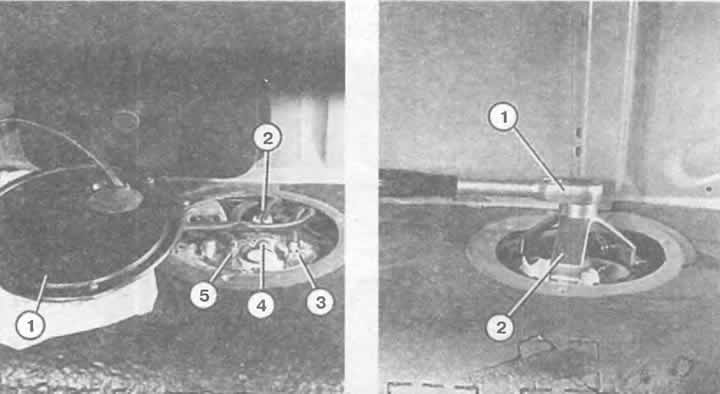
Left: First step to removing the fuel sensor. The protective cover (1) has been unscrewed. Now the…

Left: First step to removing the fuel sensor. The protective cover (1) has been unscrewed. Now the multi-pin plug (2), the fuel supply line (3) and the drain line (4), as well as the vent line (5) can be removed.

Right: The plastic union nut is unscrewed using a special tool (2) using a ratchet (1).


Mark the relative positions of the sensor and the tank. Now the fuel sensor can be lifted up a little.


From the inside of the fuel sensor, remove the fuel line and disconnect the fuel sensor plug.

Before installation, moisten the sealing ring of the protective flange with fuel.

Pay attention to the markings when installing the fuel sensor so that the pipe connections point in the correct direction and the sensor float is positioned correctly.

(The original text is available on the website: AudiManual.ru)
The article was checked by auto expert Nikita Rudakov
This article is available at russian, bulgarian, belarusian, ukrainian, serbian, croatian, romanian, polish, slovak, hungarian

Share information:
Previous articles
Audi 100 C4: Supply system
Next articles

What is the purpose of fuel tank ventilation?
Fuel tank
Fuel accumulator
Fuel line
Fuel pump


Similar articles on other Audi car models:
Fuel level sensor — removal and installation Audi 80 B3 (1986-1991, petrol)
Removal and installation the fuel pump / fuel level sensor Audi A3 Type 8L (1996-2003)
Removal and installation a fuel pump with a fuel level sensor Audi A4 B6 (2000-2006)
Fuel pump/fuel level sensor Audi A6 C5 (1997-2004)
Fuel pump / fuel level sensor Audi A8 D2 (1994-2002)
Fuel Delivery Module and Fuel Level Sensor Audi Q5 Type 8R (2008-2017)
Fuel pumping unit and fuel level indicator sensor Audi A2 (1999-2005)
Link to this page in different formats


Visitor comments

No comments yet


How much will 48 + 27 =


100(C4, 1990-1994) 
  • General information
  • User manual
  • Power unit
  • Engine repair
  • Ignition system
  • Fuel system (gasoline)
  • Fuel system (diesel)
  • Lubrication system
  • Cooling system
  • Exhaust system
  • Transmission
  • Clutch
  • Car gearbox
  • Drive shafts
  • Chassis
  • Car suspension
  • Steering
  • Wheels and tires
  • Brake system
  • Body
  • Ventilation and heating
  • Body repair
  • Electrical equipment
  • Power devices
  • Lighting and appliances
  • Electrical circuits
 
100(C4, 1990-1994, petrol) 
  • General information
  • Operation and maintenance
  • Power unit
  • Engine repair
  • Exhaust system
  • Cooling system
  • Supply system
  • Air filter
  • Mono-Motronic injection system
  • Digifant injection system
  • KE-III-Jetronic and KE-Motronic
  • MPI and MPFI injection system
  • Transmission
  • Clutch
  • Car gearbox
  • Chassis
  • Suspension and steering
  • Brake system
  • Wheels and tires
  • Body
  • Exterior
  • Interior
  • Electrical equipment
  • Fuses and relays
  • Power devices
  • Ignition system
  • Lighting and signaling
  • Equipment and devices
  • Electrical circuits
 
100(C3, 1982-1990) 
  • General information
  • User manual
  • Maintenance
  • Specifications
  • Power unit
  • Engines 4-cylinder
  • Engines 5-cylinder
  • Diesel engine
  • Cooling system
  • Power system (carburetor)
  • Power system (injector)
  • Fuel system (diesel)
  • Transistor ignition system
  • Electronic ignition system
  • Transmission
  • Clutch
  • 4 speed gearbox 014
  • 5 speed gearbox 013 and 093
  • 5 speed gearbox 016 and 012
  • Shift mechanism KP 016
  • Automatic transmission
  • Front wheel drive
  • Chassis
  • Front suspension
  • Rear suspension
  • Steering
  • Brake system
  • Body
  • Body elements
  • Electrical equipment
  • Lighting and appliances
  • Power devices
  • Electrical circuits
 
100(C3, 1982-1990, petrol) 
  • General information
  • Maintenance and operation
  • 4 cylinder engine
  • Engine repair
  • Cooling and lubrication system
  • Supply system
  • Ignition system
  • 5 cylinder engine
  • Engine repair
  • Cooling and lubrication system
  • Supply system
  • Ignition system
  • Transmission
  • Clutch and drive shafts
  • 4 speed gearbox 014
  • 5 speed gearbox 013 and 093
  • 5 speed gearbox 016 and 012
  • Automatic gearbox
  • Chassis
  • Steering
  • Front suspension
  • Rear suspension
  • Brake system
  • Body
  • Body elements
  • Doors, locks and windows
  • Body repair
  • Electrical equipment
  • Equipment and devices
  • Power devices
  • Electrical circuits
 
100(C3, 1982-1990, diesel) 
  • General information
  • User manual
  • Maintenance
  • Troubleshooting
  • Power unit
  • Engine in a car
  • Engine removed
  • Cooling system
  • Fuel system
  • Exhaust system
  • Starting and charging
  • Preheating
  • Transmission
  • Clutch
  • Mechanical gearbox
  • Automatic gearbox
  • Drive shafts
  • Chassis
  • Brake system
  • Suspension
  • Steering
  • Body
  • Exterior
  • Interior
  • Electrical equipment
  • Equipment and devices
  • Electrical circuits
 
AudiManual.ru © 2017-2026 · Mobile version · Feedback · Sitemap: EN BG BY UA RS HR RO PL SK HU · Site search · News and articles
80 B2 · 80 B3 petrol · 80 B3 · 80 B4 · 100 C3 diesel · 100 C3 petrol · 100 C3 · 100 C4 petrol · 100 C4 · A3 Type 8L · A4 B5 petrol · A4 B5 · A4 B6 petrol · A4 B6 · A4 B7 · A4 B8 · A6 C4 · A6 C5 · A6 C5 Allroad · A8 D2 · Q5 Type 8R · Q7 Typ 4L · Audi A2 ·
This site uses cookies 🍪. Click the button to accept this fact.