
Repair Chevrolet Repair Toyota Repair Honda Repair AvtoVAZ Repair Mercedes-Benz Repair BMW Repair Opel
Home  |  Contacts  |  Sitemap  |    
English Русский
Български
Беларускі
Український
Српски
Hrvatski
Română
Polski
Slovenský
Magyar
AudiManual.ru


  • AUDI 80
  • AUDI 100
  • AUDI A3
  • AUDI A4
  • AUDI A6
  • AUDI A8
  • AUDI Q
  • OTHER
  • ARTICLES
C4 (1990-1994) C4 (1990-1994, petrol) C3 (1982-1990) C3 (1982-1990, petrol) C3 (1982-1990, diesel)

The structure and principle of operation of the electronic ignition system (Audi 100 C3)

  • Home
  • Audi 100
  • C3 (1982-1990, petrol)
  • 5 cylinder engine
  • Ignition system
  • The structure and principle of operation of the electronic ignition system
            0
Table of contents: Device ↓ Operating principle ↓

Device


The electronic ignition system includes a distributor ignition sensor with a built-in contactless sensor (pulse generator sensor), commutator and high energy ignition coil.

Like the contact ignition system gel distributor, the electronic ignition system distributor sensor has a centrifugal and vacuum ignition timing regulator. The contactless sensor assembled with a support plate and a toothed anchor has the ability to rotate depending on the vacuum supplied to the vacuum regulator.

The switch is mounted to the right front fender mudguard on an aluminum base that provides cooling.

The switch converts pulses coming from the contactless sensor into control signals. The switch consists of a cascade for generating output signals from the contactless sensor (made in the form of a trigger), ignition timing control cascade, output gain cascade, implemented according to the Darlington scheme and with a time delay.

The ignition coil, adapted to this ignition system, is installed next to the switch. The coil is covered with a plastic protective casing.
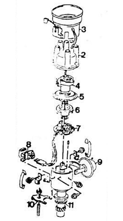
Distributor sensor details:

Distributor sensor details:
1 - sensor-distributor housing; 2 - distributor sensor cover; 3 - interference suppression screen; 4 - rotor; 5 - dust shield; 6 - toothed anchor; 7 - generator sensor of control pulses; 8 - connector; 9 - vacuum regulator; 10 - flange of the sensor-distributor housing; 11 - gasket


Operating principle


The magnetic part of the ignition distributor sensor, called the generator sensor of control pulses, consists of the actual magnetic Hall sensor and a toothed anchor fixed on the rotor

The magnetic flux in the ignition coil changes depending on the passage of the anchor teeth rotating in the pole gap of the magnetic sensor. When the anchor tooth enters the pole gap, the magnetic field of the Hall sensor integrated circuit is absent, and there is no induced current. When the anchor tooth leaves the pole gap, in accordance with the law of induction, an alternating voltage arises in the Hall sensor circuit. The circuit closes and a spark is formed.

The width of the anchor teeth corresponds to the angle of the cam.

The switch controls the ignition depending on the rotation speed of the ignition distributor shaft, the voltage of the battery, the total resistance of the ignition coil, and in any engine operating mode it produces constant voltage pulses.

Interruption of the current in the primary winding of the ignition coil by the commutator causes a sharp change in the magnetic flux in the coil and the appearance of a high voltage current in the secondary winding of the ignition coil.

(The article was copied from the website AudiManual.ru)
The article was checked by auto expert Maxim Rybakov
This article is available at russian, bulgarian, belarusian, ukrainian, serbian, croatian, romanian, polish, slovak, hungarian

Share information:
Previous articles
Audi 100 C3: Ignition system
Next articles

Ignition system — technical characteristics
Removal and installation the ignition distributor sensor
Setting the ignition timing
Ignition System Troubleshooting Diagram


Similar articles on other Audi car models:
Motronic Ignition System — Description Audi 80 B3 (1986-1991, petrol)
Electronic ignition and injection control system Audi A3 Type 8L (1996-2003)
Operating principle of the electronic engine management system Audi A4 B6 (2000-2006, petrol)
Ignition system Audi A6 C5 (1997-2004)
General recommendations for operation and repair of anti-lock… Audi A8 D2 (1994-2002)
Ignition System — Control Data Audi Q5 Type 8R (2008-2017)
Design and operating principle of the steering system Audi A2 (1999-2005)
Link to this page in different formats


Visitor comments

No comments yet


How much will 43 + 14 =


100(C4, 1990-1994) 
  • General information
  • User manual
  • Power unit
  • Engine repair
  • Ignition system
  • Fuel system (gasoline)
  • Fuel system (diesel)
  • Lubrication system
  • Cooling system
  • Exhaust system
  • Transmission
  • Clutch
  • Car gearbox
  • Drive shafts
  • Chassis
  • Car suspension
  • Steering
  • Wheels and tires
  • Brake system
  • Body
  • Ventilation and heating
  • Body repair
  • Electrical equipment
  • Power devices
  • Lighting and appliances
  • Electrical circuits
 
100(C4, 1990-1994, petrol) 
  • General information
  • Operation and maintenance
  • Power unit
  • Engine repair
  • Exhaust system
  • Cooling system
  • Supply system
  • Air filter
  • Mono-Motronic injection system
  • Digifant injection system
  • KE-III-Jetronic and KE-Motronic
  • MPI and MPFI injection system
  • Transmission
  • Clutch
  • Car gearbox
  • Chassis
  • Suspension and steering
  • Brake system
  • Wheels and tires
  • Body
  • Exterior
  • Interior
  • Electrical equipment
  • Fuses and relays
  • Power devices
  • Ignition system
  • Lighting and signaling
  • Equipment and devices
  • Electrical circuits
 
100(C3, 1982-1990) 
  • General information
  • User manual
  • Maintenance
  • Specifications
  • Power unit
  • Engines 4-cylinder
  • Engines 5-cylinder
  • Diesel engine
  • Cooling system
  • Power system (carburetor)
  • Power system (injector)
  • Fuel system (diesel)
  • Transistor ignition system
  • Electronic ignition system
  • Transmission
  • Clutch
  • 4 speed gearbox 014
  • 5 speed gearbox 013 and 093
  • 5 speed gearbox 016 and 012
  • Shift mechanism KP 016
  • Automatic transmission
  • Front wheel drive
  • Chassis
  • Front suspension
  • Rear suspension
  • Steering
  • Brake system
  • Body
  • Body elements
  • Electrical equipment
  • Lighting and appliances
  • Power devices
  • Electrical circuits
 
100(C3, 1982-1990, petrol) 
  • General information
  • Maintenance and operation
  • 4 cylinder engine
  • Engine repair
  • Cooling and lubrication system
  • Supply system
  • Ignition system
  • 5 cylinder engine
  • Engine repair
  • Cooling and lubrication system
  • Supply system
  • Ignition system
  • Transmission
  • Clutch and drive shafts
  • 4 speed gearbox 014
  • 5 speed gearbox 013 and 093
  • 5 speed gearbox 016 and 012
  • Automatic gearbox
  • Chassis
  • Steering
  • Front suspension
  • Rear suspension
  • Brake system
  • Body
  • Body elements
  • Doors, locks and windows
  • Body repair
  • Electrical equipment
  • Equipment and devices
  • Power devices
  • Electrical circuits
 
100(C3, 1982-1990, diesel) 
  • General information
  • User manual
  • Maintenance
  • Troubleshooting
  • Power unit
  • Engine in a car
  • Engine removed
  • Cooling system
  • Fuel system
  • Exhaust system
  • Starting and charging
  • Preheating
  • Transmission
  • Clutch
  • Mechanical gearbox
  • Automatic gearbox
  • Drive shafts
  • Chassis
  • Brake system
  • Suspension
  • Steering
  • Body
  • Exterior
  • Interior
  • Electrical equipment
  • Equipment and devices
  • Electrical circuits
 
AudiManual.ru © 2017-2026 · Mobile version · Feedback · Sitemap: EN BG BY UA RS HR RO PL SK HU · Site search · News and articles
80 B2 · 80 B3 petrol · 80 B3 · 80 B4 · 100 C3 diesel · 100 C3 petrol · 100 C3 · 100 C4 petrol · 100 C4 · A3 Type 8L · A4 B5 petrol · A4 B5 · A4 B6 petrol · A4 B6 · A4 B7 · A4 B8 · A6 C4 · A6 C5 · A6 C5 Allroad · A8 D2 · Q5 Type 8R · Q7 Typ 4L · Audi A2 ·
This site uses cookies 🍪. Click the button to accept this fact.