
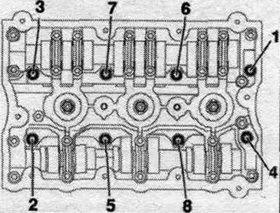
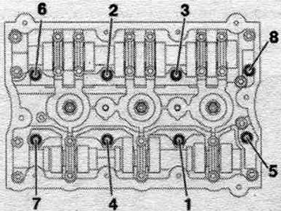
Note: The illustration shows the cylinder head of cylinder bank 2 (left).
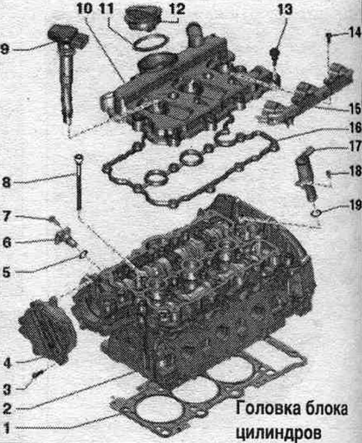
1. Cylinder head gasket; mounting position: Part number facing the cylinder head; after replacement, change the coolant and oil. 2. Cylinder head: check the curvature of the mating plane; after replacement, change the coolant and oil. 3. Bolt. 4. Vacuum pump. 5. Sealing ring: replace. 6. Hall sensor: cylinder bank 1 (right) Hall sensor "G40", cylinder bank 2 (left) Hall sensor 2 "G163". 7. Bolt. 8. Bolt: replace, observe the sequence when unscrewing. 9. Coil. 10. Cylinder head cover. 11. Gasket: replace if damaged or loose. 12. Cover. 13. Bolt: replace if seal is damaged. 14. Bolt. 15. Plug plate: for coils. 16. Cylinder head cover gasket: replace if damaged or not tightly fitted. 17. Electric. mag. valve syst. valve timing control: cylinder bank 1 (right), valve 1 of the valve timing control system "N205"; cylinder bank 2 (right), valve 2 of the timing phase control system "N208". 18. Bolt: 5 Nm. 19. Sealing ring: replace.
Left cylinder head cover - sequence and tightening torque
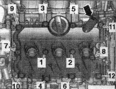
Tighten the bolts in sequence. "1...12" with a torque of 9 Nm.
Right cylinder head cover - sequence and tightening torque
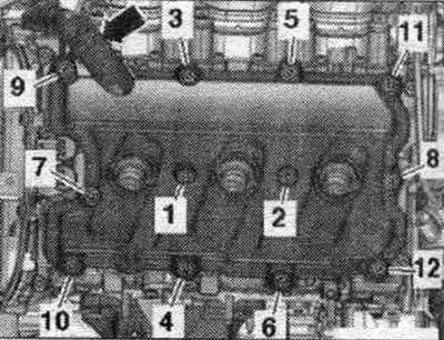
Tighten the bolts in sequence. "1...12" with a torque of 9 Nm.
Cylinder head - last, and bolt tightening torque
Bolts tightened at the tightening angle should be replaced. Tighten the bolts in 4 stages in the sequence shown.
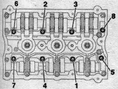
| Step | Bolts | Tightening torque/rotation angle |
| 1 | "1...8" | screw it in by hand until it stops |
| 2 | "1...8" | 40 Nm |
| 3 | "1...8" | turn 90° |
| 4 | "1...8" | turn 90° |
Take off
The engine is installed. The following describes the simultaneous removal of both cylinder heads. If you only need to remove one cylinder head, you can skip the steps for the unneeded cylinder head. During installation, all cable ties should be placed in their original locations. Relieve fuel pressure in the high pressure sector. Removing the upper coolant pipe. Remove the poly V-belt. Remove the lower part of the air intake. Disconnect the plug connectors from the injection nozzles. Remove the appropriate timing chain from the camshafts.
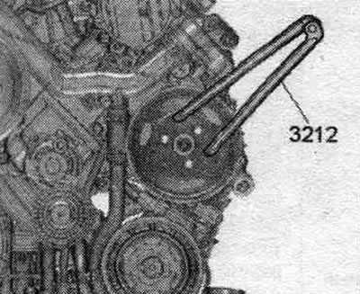
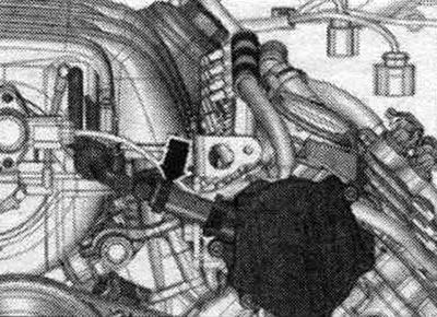
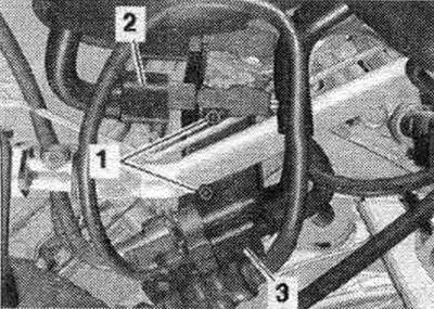
A/m with hydraulics. power steering: Unscrew the bolts of the poly V-belt pulley of the impeller pump, for this use a 2-hole wrench "3212" as a counter support.
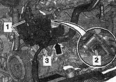
Unscrew bolts "1" and "2", put the impeller pump aside. The figure shows the installation. position on a vehicle with dynamic steering. "Pos. 3" and "arrow" should not be taken into account.
All
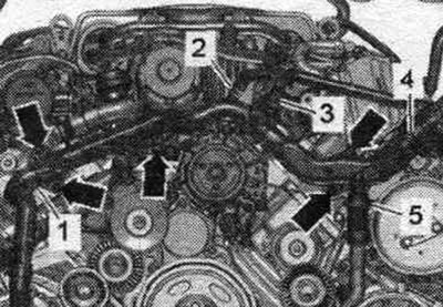
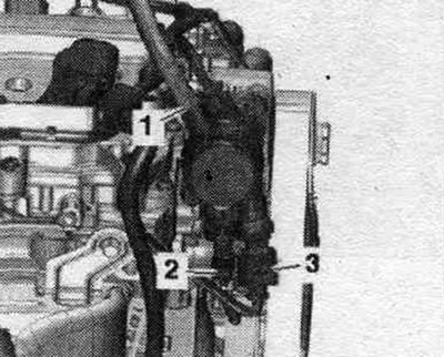
Disconnect connector "3" of coolant temperature sensor "G62". Unscrew bolts "arrows". Disconnect the hose from the front pipe of the system. cooling by lifting clamps "1, 4" and loosening clamp "2". Ignore "Pos. 5".
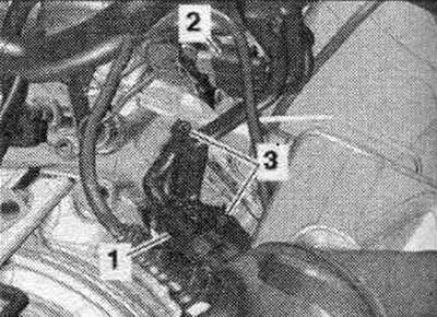
Unscrew the fastening "1" and move the fuel supply line away. highway to the side. Disconnect plug connectors "2" and "3".
Unscrew the "arrow" bolt and remove the oil dipstick guide tube.
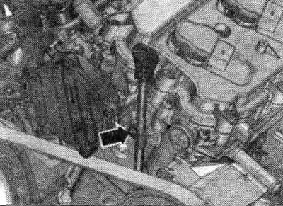
Remove the vacuum hose from the vacuum pump by disconnecting the "arrow" clamp and releasing the vacuum hose.
Unscrew the "arrow" bolts behind the cylinder head: left cylinder head: 3 bolts, right cylinder head: 4 bolts.
Loosen the cylinder head bolts in sequence. "1...8". Unscrew the bolts, carefully remove the cylinder head and place it on a soft pad.
Install
Caution! Risk of damage to the sealing surface. Carefully remove any remaining sealant from the cylinder head and cylinder block. Avoid creating long scratches or burrs. Risk of damage to the cylinder block. There should be no oil or coolant in the blind holes of the cylinder head bolts. Risk of a leaky cylinder head gasket. Carefully remove any remaining sanding and grinding material. The new cylinder head gasket should be removed from the packaging immediately before installation. To prevent damage to the silicone layer and the grooves of the cylinder head gasket, handle the gasket with particular care. Risk of damage to open valves. When installing a replacement cylinder head, remove the plastic base to protect the exposed valves only when it comes into direct contact with the cylinder head. There is a risk of damage to the valves and piston crowns after working on the valve train. To ensure that no valves are touching the cylinder head during operation, carefully rotate the engine at least 2 revolutions. Replace any bolts that were overtightened. Replace self-locking nuts, lip seals, gaskets and seals. rings. Pay attention to different sealants for cylinder head mounting surfaces and bolts. Before installing a replacement cylinder head, lubricate the mating surfaces of the hydraulic lifters, rocker arms, and camshaft running surfaces with oil. To secure all hose connections, use clamps of the appropriate series. When replacing the cylinder head or cylinder head gasket, replace the coolant and oil.
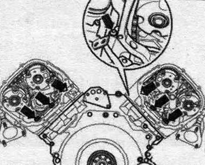
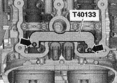
Lock the camshafts on both cylinder heads with the camshaft retainer "T40133" in the "TDC" position "arrows" (25 Nm). The camshaft retainer "T40133" is installed correctly if the holes facing the cylinder head bolts remain free.
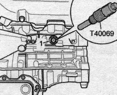
Crankshaft "1" is fixed in the "TDC" position using the locking screw "T40069".
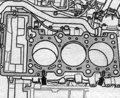
Insert new seals and gaskets. front coolant pipe rings. Install the cylinder head seal. Mounting position; the marking "on top" or the part number must be visible. Pay attention to the centering bushings "arrows" in the cylinder block. Install the cylinder head.
Tighten the cylinder head bolts.
Tighten the lower timing chain cover "arrow" bolts; left cylinder head: 3 bolts, right cylinder head: 4 bolts. Tightening the cylinder head mounting bolts after repair work is not necessary. Installation in reverse order. Install the lower part of the air intake. Install the poly V-belt. Install the impeller pump. Install the drive chains on the camshafts. Install the dipstick guide tube. Install the front coolant pipe. Install the upper coolant pipe. Change the oil. Replace the coolant.
Compression check
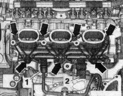
Oil temperature is not less than 30°C. Battery voltage is at least 12.5 V. Remove all coils. Disconnect electrical connector "2" from the injectors at the rear of the left cylinder head. "Pos. 1, 3" do not take into account.
Disconnect electrical connector "2" from the injectors at the rear of the right cylinder head. "Pos. 1, 3" do not take into account.
Remove the spark plugs using a 3122B spark plug wrench. Check the compression using a VAG 1763 compression tester. The second mechanic should depress the accelerator pedal and let the starter run until the pressure on the compression tester stops rising. Conduct a check of each cyl..
| Compression values | Bar of excess pressure |
| New | 11,0...14,0 |
| Maximum tolerance | 10,0 |
| The difference between [cylinders | max 3.0 |
Installation
Installation in reverse order. Install spark plugs. If the engine is started with the electrical connectors disconnected, an entry is made in the event recorder of the engine control unit: Generate readiness code in the Guided Functions mode.
(A link to the original source is available on the website: «AUDIMANUAL.ru»)