



Table of contents: Slave disk ↓ Crankshaft ↓ "TDC" mark cap ↓ Oil pressure regulating valve "N428" ↓ Sealant layer for camshaft frame,… ↓ Pistons and connecting rods ↓
Slave disk
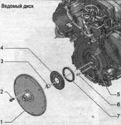
1. Driven disk: with bearing flange; check the working surfaces of the bearing mounting flange and the clutch module holes for cracks and entry holes. 2. Bolt: replace; 60 Nm + 90°. 3. Needle bearing: mounting position: closed side facing the engine. 4. Engine speed sensor ring gear "G28". 5. Crankshaft. 6. Dowel pin. 7. Crankshaft oil seal on the gearbox side.
Crankshaft
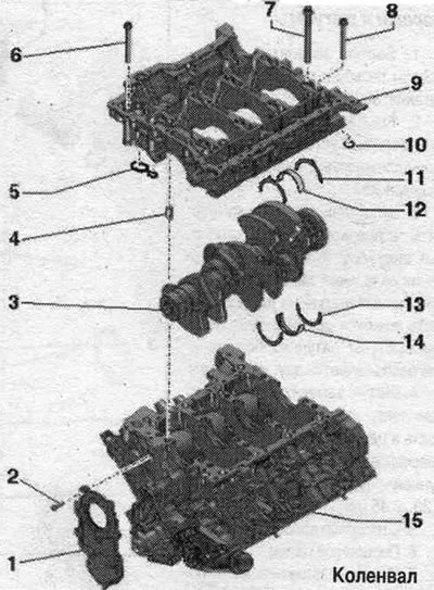
1. Sealing flange on the pulley side.
2. Bolt.
3. Crankshaft.
4. Guide bushing: 4 pcs.; install into the camshaft frame.
5. Gasket: replace.
6. Bolt: for the seating surfaces of the camshaft frame to the cylinder block; bolts of different lengths and with different heads.
7. Extended bolt, long threaded section: for the inner row of the camshaft frame; replace.
8. Short bolt, short threaded section: for the outer row of the camshaft frame.
9. Camshaft frame: with oil pressure regulating valve "N428"; to dismantle, remove the chain tensioner bar of the control mechanism drive.
10. Lip seal: replace.
11. Crankshaft axial locking bushing: crankshaft bearing 3 only; mounting position: oil groove facing outward; take into account the fixation of the camshaft in the frame.
12. Bearing insert: for camshaft frame without oil groove; replace used liners; install in the proper position; install new crankshaft frame bearing shells with the correct color markings.
13. Crankshaft axial locking bushing: crankshaft bearing 3 only; mounting position: oil groove facing outward; take into account the fixation of the camshaft in the frame.
14. Bearing insert: for cylinder block with oil groove; replace used liners; install in the proper position; install new bearing shells with the correct color markings.
15. Cylinder block.
"TDC" mark cap
Replace the seal. ring.
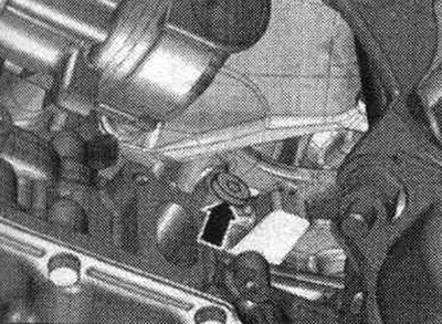
Tighten the threaded screw "arrow" to a torque of 14 Nm.
Oil pressure regulating valve "N428"
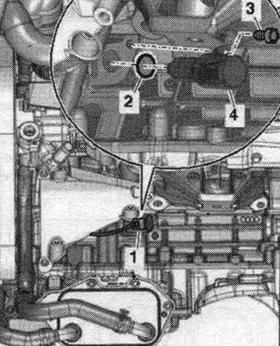
1. Electrical connector; 2. Replace the seal. o-ring; 3. Bolt, 9 Nm; 4. Oil pressure regulating valve "N428".
Sealant layer for camshaft frame, position of mounting bushings
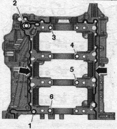
Clean the sealing surfaces from oil and grease. Apply a bead of "arrow" sealant to the clean camshaft frame mounting surfaces as shown in the figure. The groove of the seating surface must be filled with sealant. The sealant beads should protrude 1.5–2.0 mm above the mounting surface. Apply seals "1" and "2." Check that centering bushings "3–6" are installed in the camshaft frame as shown in the figure.
Install the guide frame
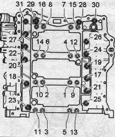
Bolts tightened at the tightening angle should be replaced. Insert long bolts into the inner row of the camshaft frame. Tighten the bolts in 3 stages in the sequence shown.
| Step | Bolts | Tightening torque/rotation angle |
| 1 | "1...16" | 50 Nm |
| 2 | "1...16" | turn 90° |
| 3 | "17...31" | 23 Nm |
Accessories for main bearing shells installed in the cylinder block
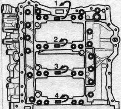
At the factory, bearing liners of the correct thickness are installed in the cylinder block. Colored dots on the bearing shell are used to mark the thickness of the bearing shells. The belonging of the bearing shells to the cylinder block is indicated by a letter next to the corresponding bearing.
| Letter on the camshaft frame | Bearing color |
| R = | red |
| G = | yellow |
| B = | blue |
| S = | black |
Camshaft frame bearing shells accessory
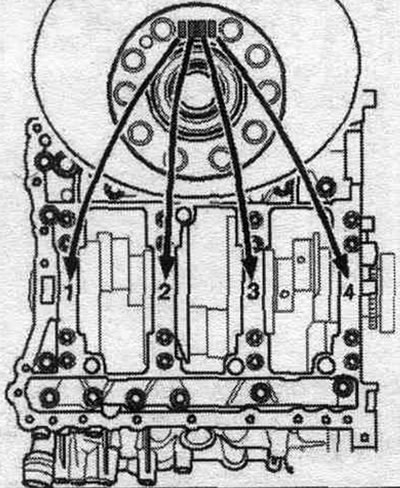
At the factory, bearing shells of the correct thickness are installed in the camshaft frame. Colored dots on the bearing shell are used to mark the thickness of the bearing shells. The correspondence of the bearing shells to the camshaft frame is indicated by letters on the flywheel flange. The first letter in the row is for bearing "1", the second letter is for bearing "2", and so on.
| Letter on the crankshaft | Bearing color |
| R = | red |
| G = | yellow |
| B = | blue |
| S = | black |
Crankshaft dimensions
| Grinding size | Crankshaft main bearing journal, diameter in mm | Crankshaft main journal, diameter in mm |
| Nominal size | 65 000 - 0,022; 65,000 - 0,042 | 56 000 - 0,022; 56,000 - 0,042 |
Pistons and connecting rods
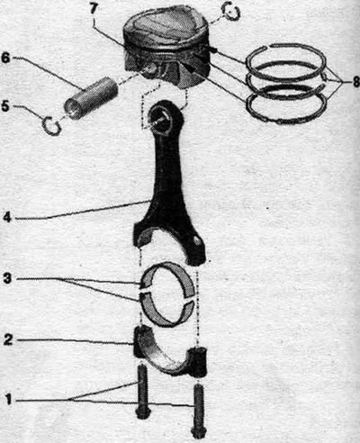
1. Bolts: replace, lubricate the threads and mating surface with oil; 50 Nm + 90°.
2. Connecting rod cap: Mark for reinstallation; mark the cylinder and connecting rod affiliation with paint.
3. Bearing liners: ensure that the locking tabs are securely seated. Replace used liners. Repair liners are available for machined crankshaft journals; the protrusions of the connecting rod bearings are located one above the other.
4. Connecting rod: replace only the entire set; mark the cylinder and connecting rod cap with paint; axial clearance in each connecting rod pair, new parts: 0.20...0.45 mm.
5. Retaining ring: replace.
6. Piston pin.
7. Piston: mark installation. position and belonging to the cylinder; if cracks or burrs appear on the bottom or skirt, replace the piston.
8. Piston rings: Remove and install using standard piston ring pliers; installation position: the "TOP" marking or the side with the inscription is directed towards the piston bottom; spread the locks around the circumference at 120°.
Mounting position of the piston
Risk of destruction of the piston bottom coating. To ensure correct subsequent installation of used pistons, mark the piston to cylinder alignment with paint. Do not make notches on the piston crown with a center punch or similar tools.
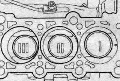
Installation position: arrows on the piston crowns point towards the belt pulleys.
Mark the connecting rods
The connecting rod must be replaced as an assembly only. Mark the connecting rods and connecting rod caps with paint for reassembly to indicate their correspondence to each other and to the cylinder "arrow".
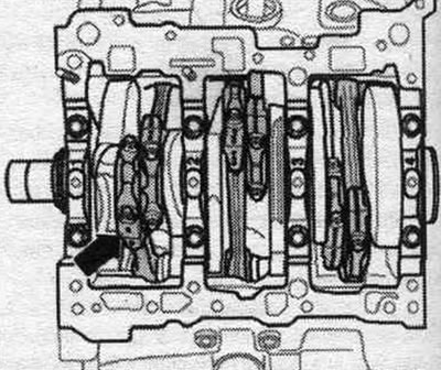
Mounting position of the connecting rod
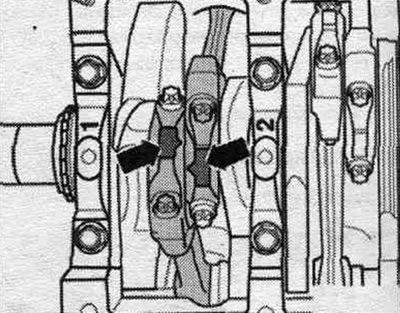
The toes of the "arrows" on the ground surfaces of pairs of connecting rods "1 and 2", "3 and 4", and also "5 and 6" must be facing each other.
Piston cooling oil nozzle
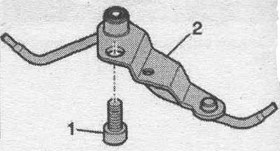
1. Insert the bolt with threaded varnish and tighten to a torque of 9 Nm 2. Oil nozzle with valve (opening pressure 2...2.4 bar excess pressure).
Caution! Risk of damage to oil injectors. Do not bend the oil nozzles. Bent oil injection nozzles must be replaced.