
Table of contents: Chain drive covers ↓ Removal and installation the left… ↓ Removal and installation the lower… ↓ Camshaft chain drives ↓ Removal and installation camshaft… ↓ Timing chain ↓ Removal and installation the chain… ↓ Attachment drive chain ↓ Balance shaft ↓ Removal and installation the balance… ↓
Chain drive covers
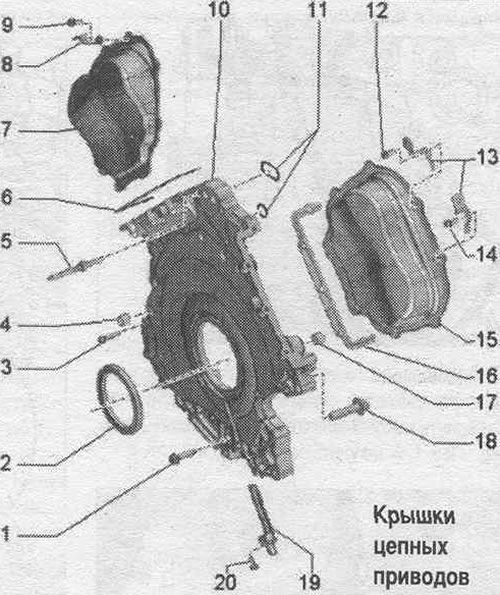
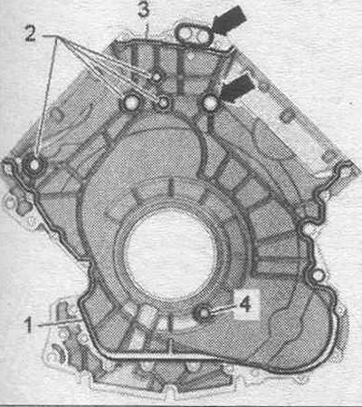
1. Bolt: replace. 2. Crankshaft oil seal, gearbox side. 3. Bolt: replace. 4. Guide sleeve: 2 pcs. 5. Grub screw. 6. Left cylinder head gasket. 7. Left timing chain cover. 8. Bracket: for wiring harness. 9. Bolt: replace. 10. Lower drive chain cover. 11. Gaskets: replace. 12. Bolt. 13. Connector bracket. 14. Bolt: replace. 15. Right timing chain cover. 16. Right cylinder head gasket. 17. Guide sleeve: 2 pcs. 18. Bolt. 19. Engine speed sensor "G28". 20. Bolt.
Left timing chain cover - last and bolt tightening torque
Bolts tightened at the tightening angle should be replaced. Tighten the bolts in 2 stages in the sequence shown:
| Step | Bolts | Tightening torque/rotation angle |
| 1 | "1...8" | 5 Nm |
| 2 | "1...8" | turn 90° |
Right timing chain cover - last and bolt tightening torque
Bolts tightened at the tightening angle should be replaced. Tighten the bolts in 2 stages in the sequence shown.
| Step | Bolts | Tightening torque/rotation angle |
| 1 | "1...8" | 5 Nm |
| 2 | "1...8" | turn 90° |
Lower drive chain cover - bolt tightening torque and sequence
Bolts tightened at the tightening angle should be replaced. Tighten the bolts in 8 steps as follows.
| Step | Bolts | Tightening torque/rotation angle |
| 1 | "arrows" | 3 Nm |
| 2 | "1...10" | crosswise 3 Nm |
| 3 | "1, 2, 4, 5, 7" and "arrows" | turn 90° |
| 4 | "8, 9, 10" | 8 Nm |
| 5 | "8, 9, 10" | turn 90° |
| 6 | "3" | 16 Nm |
| 7 | "6" | 20 Nm |
| 8 | "6" | turn 90° |
Removal and installation the left and right timing chain covers
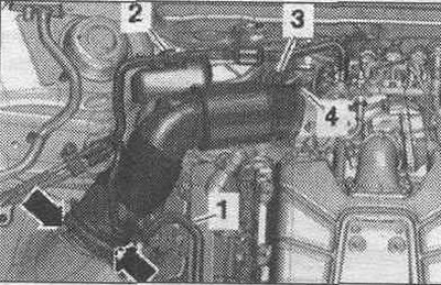
During installation, all cable ties should be placed in their original locations. Remove the rear engine cover "2" upwards. Remove the corresponding secondary air combination valve.
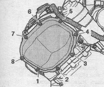
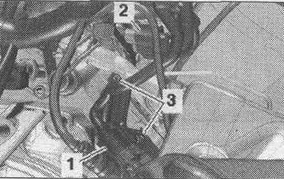
Left timing chain cover: Remove bolts "1" and place the bracket with connectors aside. "Pos. 2, 3" do not take into account.
Remove bolts "1...8". Carefully loosen and remove the left timing chain cover from the bonding area.
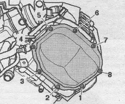
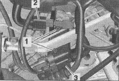
Right timing chain cover: Release fuel. hose "1" and hose "2" to the activated carbon absorber on the air duct. Remove vacuum hose "3" from the air duct connection. Remove the air duct hose by loosening the hose clamp "4" and opening the clamps "arrow".
Unscrew bolts "3" and put the bracket with connectors aside. "Pos. 1, 2" do not take into account.
Unscrew bolts "1...8". Carefully separate and remove the right drive chain cover from the bonding area.
Installation
The bolts tightened with the tightening angle should be replaced; Replace the seal. rings. Remove old sealant from the mating surfaces. Cover exposed engine parts. Remove any remaining sealant from the timing chain covers, cylinder block and cylinder head, for example, using a rotating brush attachment with plastic bristles. Clean the sealing surfaces from oil and grease. Observe the expiration date of the sealant. Cut off the tube tip along the front mark (opening diameter approx. 2 mm). Risk of blockage of the system channels. lubrication when there is excess sealant. The sealant bead should not be thicker than the specified size. Apply a bead of "arrow" sealant to the clean seating surface of the left timing chain cover as shown in the figure. Sealant bead thickness: 2.5 mm. Timing chain covers must be installed within 5 minutes of sealant application.
Insert the left timing chain cover and tighten the bolts. Apply a bead of "arrow" sealant to the clean seating surface of the right cover
drive chain as shown in the figure. Thickness of sealant bead: 2.5 mm. Insert the right timing chain cover and tighten the bolts. Installation in reverse order. To secure all hose connections, use clamps of the appropriate series. Install the secondary air combination valve.
Removal and installation the lower timing chain cover
The gearbox has been removed. The oil has been drained. Follow the instructions when disconnecting the battery terminals. Turn off the ignition and remove the key from the ignition switch. Disconnect ground wire "2" from the battery terminal. Remove the driven disk. Remove the camshaft chain protective covers on the left and right. Remove the oil filter housing.
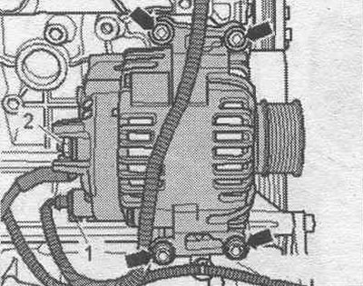
Remove the generator.
Disconnect the starter electrical connector "3", move the lock back and press the stopper down. Unscrew nut "2" of the electrical wire and remove the starter. "Pos. 1, 4" do not take into account.
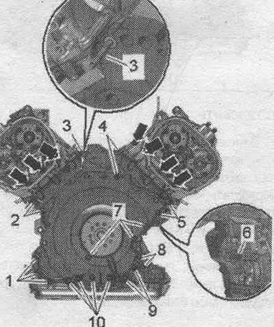
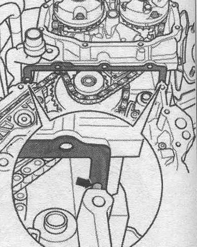
Loosen the "arrow" bolts. Loosen bolts "1...10" crosswise and unscrew them. Carefully separate and remove the lower drive chain covers from the bonding area. Press the crankshaft seal from the gearbox side out of the lower timing chain cover.
Install
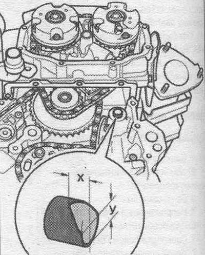
Replace gaskets, o-rings and seals. o-rings. Remove the right upper fitted bushing from the cylinder block. File the edges of the centering bushings as shown in the figure. Dimension "x" = 6.5 mm. Dimension "y" = 8 mm. Install the bushing on the cylinder block so that the machined side faces up. This bevel makes it easier to install the lower chain drive cover when the cylinder block is installed.
Remove any remaining sealant from the timing chain cover, cylinder block and cylinder head, for example, using a rotating brush attachment with plastic bristles. Clean the sealing surfaces from oil and grease. Before assembling the gearbox, clean the threaded holes of the power unit in the cylinder block with a tap. Clean the "arrow" holes in the cylinder head gaskets from the old sealant. When the cylinder head is installed, the holes in its gasket are only half visible.
Risk of damage to the cylinder head gasket. Bend the ends of the cylinder head gasket slightly, do not twist them. A broken cylinder head gasket should be replaced. Bend the ends of the cylinder head gasket slightly downwards, just enough to allow the top sealing surface of the gasket and the cylinder head to be cleaned. Clean the top and bottom of the cylinder head gasket of oil and grease.
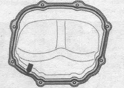
Cut off the tube tip along the front mark (opening diameter approx. 2 mm). The sealant must be applied to several areas of the engine as described below. Apply a thin layer of sealant to the mating surfaces on the top and bottom of the cylinder head gaskets; to do this, slightly bend the gaskets down again "arrows". Use a flat object, for example a feeler gauge, to apply the sealant to the surface between the cylinder head and the gasket. Fill the cleaned holes marked "arrow" in the cylinder head gaskets with sealant. Apply beads of sealant "1...4" to the clean seating surfaces of the lower timing chain cover, as shown in the figure. The groove of the seating surface must be filled with sealant. The sealant beads should protrude 1.5–2.0 mm above the seating surface. Apply bead "2" of sealant as shown in the figure, even if the groove is interrupted. The timing chain cover must be installed within 5 minutes of applying the sealant. Insert the "arrow" gaskets into the grooves of the lower cover of the drive chains. Install the lower chain cover, positioning the cover diagonally from below against the cylinder block and cylinder head mating surface. Be careful not to damage the cylinder head gaskets during installation. Tighten the lower chain cover bolts.
Installation in reverse order. Install the crankshaft oil seal on the gearbox side. Install the starter and generator. Install the oil filter housing. Install the timing chain guards on the left and right. Install the slave disk. Fill with oil and check its level.
Camshaft chain drives
Left camshaft timing chain
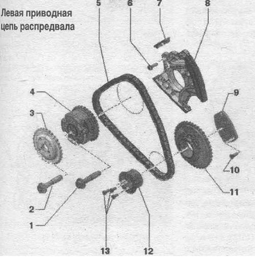
1/2. Bolt: replace; 80 Nm + turn 90° further. 3. Exhaust camshaft sprocket. 4. Intake camshaft phase shifter: marked "Intake". 5. Left camshaft drive chain: mark the direction of rotation for reverse installation, remove the chain from the camshafts. 6. Bolt: 9 Nm. 7. Runner. 8. Left camshaft chain tensioner. 9. Drive sprocket support plate. 10. Bolt: replace; 8 Nm + turn further by 45°. 11. Left camshaft timing chain sprocket. 12. Drive sprocket support pins: for camshaft drive chain on the left. 13. Bolts.
Right camshaft timing chain
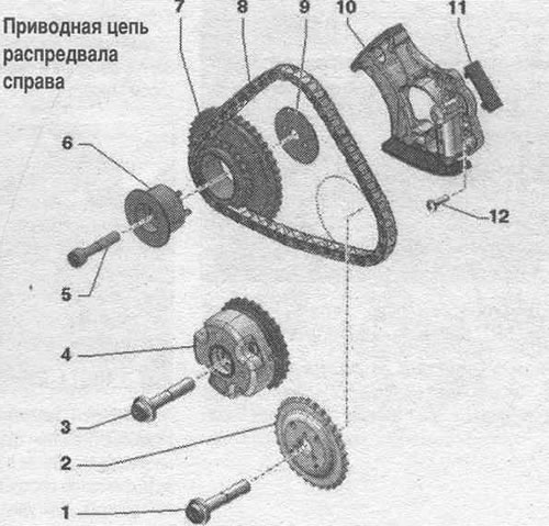
1. Bolt: replace; 80 Nm + turn 90° further. 2. Exhaust camshaft sprocket. 3. Bolt: replace; 80 Nm + 90° further. 4. Intake camshaft phase shifter: marked "Intake". 5. Bolt. 6. Drive sprocket support pins: for camshaft drive chain on the right, asymmetrical design. 7. Drive sprocket for camshaft drive chain on the right. 8. Right camshaft timing chain: Mark the direction of rotation for reverse installation, remove the chain from the camshafts. 9. Timing chain sprocket axial locking washer: for right camshaft timing chain, asymmetrical design. 10. Right camshaft timing chain tensioner. 11. Runner. 12. Bolt: 9 Nm.
Removal the chains from the camshafts
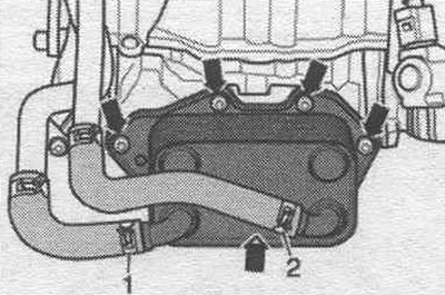
The following description assumes that the camshaft timing chains remain on the engine. If work is performed on only one of the cylinder heads, then the timing chain cover of the other cylinder head does not need to be removed. Remove the appropriate timing chain cover. Remove the corresponding cylinder head cover. Remove the poly V-belt from the tensioner and relieve the tensioner. Install the VAG 1782 oil extraction and collection device under the engine. Remove the arrow screws and tie the engine oil cooler to the side with coolant hoses 1 and 2 connected.
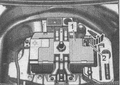
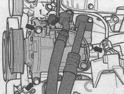
Unscrew the "arrow" bolts securing the air conditioning compressor. Remove the air conditioning compressor with the connected pipes from the bracket and tie it to the left side member. "Pos. 1" should not be taken into account.
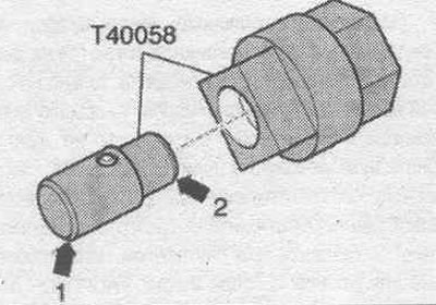
Insert the guide pins of the adapter "T40058" as shown below: the large diameter "arrow 1" faces the engine, the small diameter "arrow 2" faces the adapter.
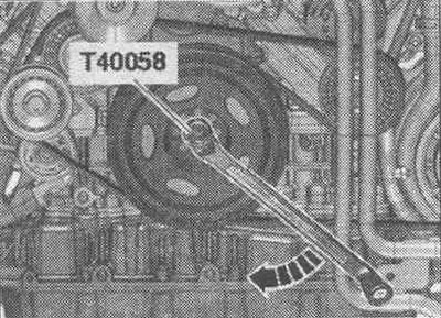
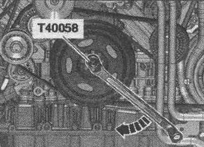
Remove, if necessary, the front noise-insulating cover "1". Turn the crankshaft using the "T40058" adapter and a bent socket wrench in the direction of engine rotation "arrow" to "TDC".
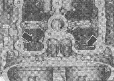
The threaded holes "arrows" in the camshafts must point upwards.
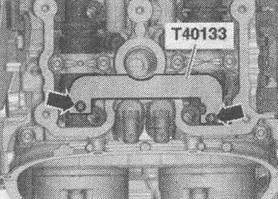
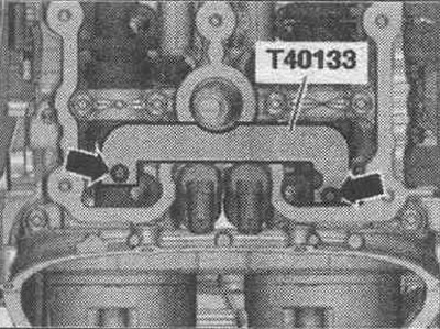
Install the camshaft retainers "T40133" on both cylinder heads and tighten to 25 Nm "arrows". The illustration shows the left cylinder head.
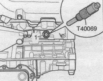
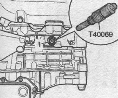
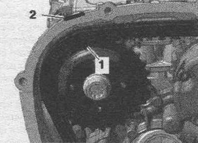
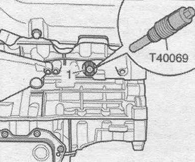
Unscrew the threaded plug "arrow" of the "TDC" mark of the crankshaft from the cylinder block.
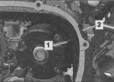
Screw the fixing bolt "T40069" into the hole with a torque of 20 Nm; if necessary, to completely center the bolt, slightly turn the crankshaft "1" in both directions.
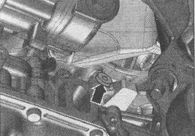
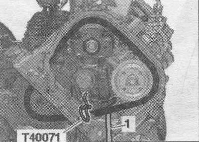
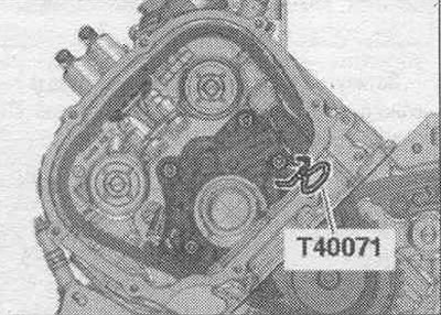
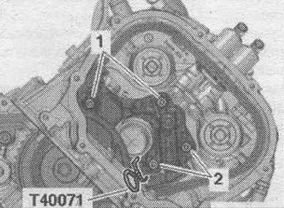
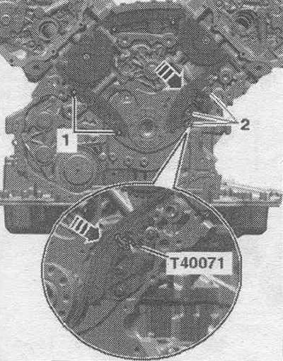
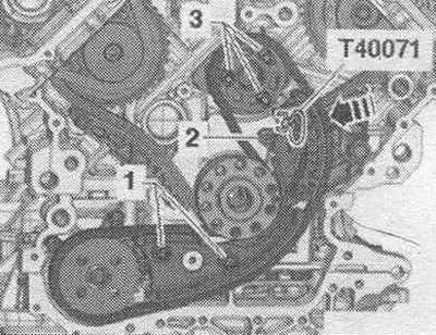
The camshaft chain tensioners are equipped with an oil damper, so apply pressure to them gradually with uniform force. Move the sliding bar of the left camshaft chain tensioner with screwdriver "1" inward until it stops and secure the tensioner with the clamp "T40071".
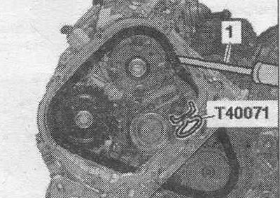
Move the sliding bar of the right camshaft chain tensioner with screwdriver "1" inward until it stops and secure the tensioner with the lock "T40071".
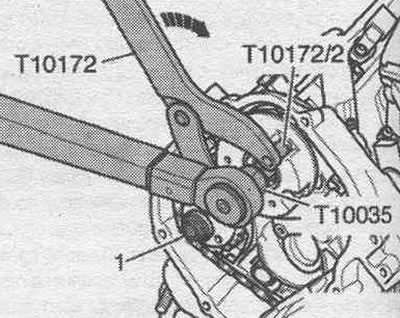
Risk of damage to camshafts. To loosen the phase shifter bolts or camshaft gear, never use the "T40133" camshaft locking tool as a counter support. To hold the corresponding phase shifter, install the "T10172" counter-support with the "T10172/2" pin and unscrew it with the "T10035" attachment. Ignore "Pos. 1" and the "arrow".
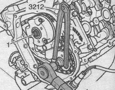
To hold the corresponding sprocket, install the wrench under the 2 holes "3212" and unscrew the bolt with the "T10035" socket. Ignore "Pos. 1" and the "arrow".
Mark mont. position of the phase shifter and camshaft sprocket for reinstallation. Unscrew bolts "1" and "2" on the cylinder head on the left and remove the phase shifter and camshaft sprocket.
Mark mont. position of the phase shifter and camshaft sprocket for reinstallation. Unscrew bolts "1" and "2" on the cylinder head on the right and remove the phase shifter and camshaft sprocket.
Install
Bolts tightened at the tightening angle should be replaced. The chain drive is installed. Crankshaft "1" is fixed in the "TDC" position using the locking screw "T40069".
Lock the camshafts on both cylinder heads with the camshaft retainer "T40133" in the "TDC" position "arrows" (25 Nm). The illustration shows the left cylinder head.
The camshaft sprockets should only be installed in the following order. Install the camshaft sprockets according to the marks made during removal. When installing the sprocket, make sure that the pins on the sprockets engage in the holes on the camshafts "arrows".
Turn the sprocket on the camshaft counterclockwise to the stop "arrow".
Mark "1" should be located opposite the installation window "2".
Phase shifters should only be installed in the following order. Install the phase shifter according to the marks made during removal. Groove "1" in the phase shifter must be located opposite the installation window "2".
Install the left drive chain onto the drive sprocket, phase shifter, and camshaft sprocket, and loosely tighten bolts "1" and "2." The phase shifter and camshaft chain drive sprocket can be rotated further on the camshaft; they should not be warped. Remove the "T40071" locking pin. Install the phase shifter on the right cylinder head in accordance with the markings made during removal. Install the right drive chain onto the drive sprocket, phase shifter, and camshaft sprocket, and loosely tighten bolts "1" and "2." The phase shifter and camshaft chain drive sprocket can be rotated further on the camshaft; they should not be warped. Remove the locking pin "T40071". Install the 2-hole wrench "3212" onto the right exhaust camshaft sprocket. The second mechanic must maintain the pre-tension of the camshaft drive chain by pressing the sprocket in the direction of the arrow. Tighten the bolts as follows, while the camshaft chain sprocket is still under pre-tension.
| Step | Bolt | Tightening torque |
| 1 | Exhaust camshaft 80 Nm | |
| 1 | "1" | Intake camshaft 80 Nm |
Place the counter support "T10172" with the pin "T10172/2" against the phase shifter of the left intake camshaft. The second mechanic must maintain the pre-tension of the camshaft drive chain by pressing the counter support in the direction of the arrow. Tighten the bolts as follows, while the phase shifter is still pre-tensioned.
| Step | Bolt | Tightening torque |
| 1 | Exhaust camshaft 80 Nm | |
| 1 | "1" | Intake camshaft 80 Nm |
Tighten the phase shifter bolts and camshaft chain sprocket on the left cylinder head as follows.
| Step | Bolt | Tightening torque |
| 2 | "1" | To the exhaust camshaft at the final moment |
| 2 | "2" | To the intake camshaft at the final moment |
Tighten the phase shifter bolts and camshaft chain sprocket on the right cylinder head as follows.
| Step | Bolt | Tightening torque |
| 2 | "1" | To the intake camshaft at the final moment |
| 2 | "2" | To the exhaust camshaft at the final moment |
Remove the camshaft retainers "T40133" from both cylinder heads "arrows". The illustration shows the left cylinder head. Unscrew the locking bolt "T40069". Turn the crankshaft using the adapter "T40058" and the 180° offset open-end wrench 2 turns in the direction of engine rotation "arrow" so that the crankshaft returns to the "TDC" position. If the crankshaft has gone past "TDC", turn it back 30° and set it to "TDC" again.
The threaded holes "arrows" in the camshafts must point upwards. Install the camshaft retainers "T40133" on both cylinder heads and tighten to 25 Nm "arrows". Screw the locking bolt "T40069" straight into the hole. The fixing bolt "T40069" must fit into the hole on the crankshaft "1", otherwise repeat the adjustment. Remove the camshaft locks from both cylinder heads. Remove the lock screw.
Installation in reverse order. Screw in the threaded plug for the TDC mark on the crankshaft. Install the air conditioning compressor. Install the engine oil cooler. Install soundproofing. Install the poly V-belt. Install the cylinder head covers. Install the timing chain guards on the left and right.
Removal and installation camshaft drive chains
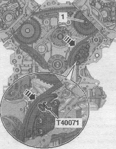
The gearbox is removed. Remove the lower cover of the drive chains. Remove the cylinder head covers. Remove the corresponding drive chain from the camshafts. Risk of failure due to reverse running of the camshaft drive chain already in use. For reassembly, mark the direction of travel of the left and right drive chains with an arrow, using paint for this. Do not score the camshaft timing chains with a center punch or similar tools. Remove the locking pin "T40071" and remove the left drive chain.
Unscrew bolts "1" and "2" and remove the right chain tensioner.
Press the drive chain tensioner slider in the direction of the arrow and secure the tensioner with the locking pin "T40071". Remove bolt "1" of the drive sprocket. Remove the drive sprocket with the support pin and pull the right camshaft drive chain upwards.
Install
If the chain tensioner actuator was removed during assembly, install it in the correct position: the hole in the lower part of the housing is directed towards the chain tensioner, and the piston is directed towards the tensioner bar. Replace bolts that were tightened with additional tightening. Install the camshaft drive chain on the left according to the markings made during removal. as shown in the figure. Press the timing chain tensioner slider down on the left and secure it with the T40071 locking pin. Route the camshaft chain up toward the cylinder head, paying attention to the marks made during removal. Install the drive sprocket. Tighten bearing housing bolt "1". Remove the locking pin "T40071". Ignore the "arrow". Insert the chain tensioner into the cylinder head on the right and install the camshaft drive chain. Tighten bolts "1" and "2". Installation is in reverse order. Install the drive chains on the camshafts. Install the lower drive chain cover.
Timing chain
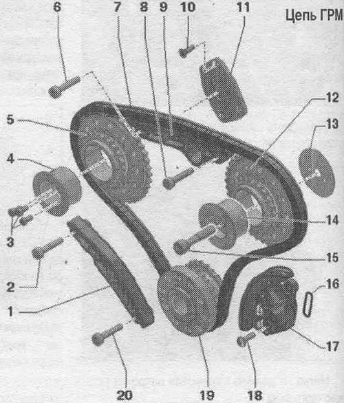
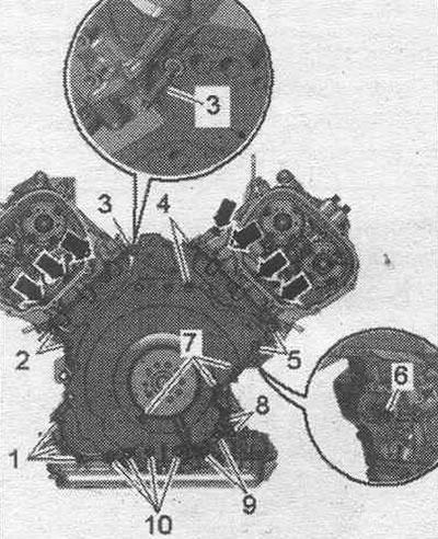
1. Dampener bar. 2. Bolt: replace; 10 Nm + tighten by 90°. 3. Bolts: replace; 5 Nm + turn further by +60°. 4. Drive sprocket support pins. 5. Left drive chain drive sprocket. 6. Bolt: replace; 10 Nm + 90° further. 7. Timing chain: Mark the direction of rotation for reinstallation. 8. Bolt: replace; 10 Nm + turn further by 90°. 9. Guide bar. 10. Bolt: replace; 8 Nm + 45° further. 11. Drive sprocket support plate: for camshaft timing chain on the right, asymmetrical design. 12. Right drive chain drive sprocket. 13. Crankshaft axial locking liner: asymmetric design. 14. Drive sprocket support pins: asymmetrical design. 15. Bolt: 30 Nm + tighten by 90°. 16. Gasket: replace. 17. Chain tensioner. 18. Bolt: 9 Nm. 19. Crankshaft. 20. Bolt: replace; 10 Nm + turn further by 90°.
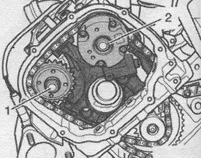
Mounting position of the drive chain sprocket bearing housing on the right
The dowel pins in the bearing cap bolts "3" of the right camshaft drive sprocket must fit into the hole in the dowel washer "1" and the cylinder block.
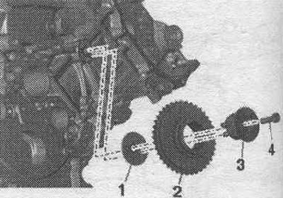
2. Drive sprocket for camshaft drive chain on the right; 4. Bolt.
Removal and installation the chain drive of the control mechanism
The gearbox is removed. Remove the lower cover of the drive chains. Remove the chains from the camshafts. Remove the auxiliary chain drive. units. Press the chain tensioner slider in the direction of the arrow and secure the chain tensioner with the T40071 locking pin. Risk of failure due to reverse rotation of an already used drive chain. For reassembly, mark the direction of the drive chain with an arrow, using paint for this. Do not make notches on the chain drive with a center punch or similar tools. Unscrew bolt "1" and remove the damper bar. Unscrew bolts "2" and remove the chain tensioner. Remove the chain drive of the control mechanism.
Install
Installation in reverse order. Bolts tightened at the tightening angle should be replaced. Install the control mechanism drive chain onto the chain drive sprockets, using the marks made during removal. Install the tensioner bar and tighten the bolts "1". Install the chain tensioner and tighten the bolts "2". Move the drive chain tensioner guide - in the direction of the arrow - and remove the locking pin "T40071". Install the auxiliary chain drive. units. Install the drive chains on the camshafts. Install the lower drive chain cover.
Attachment drive chain
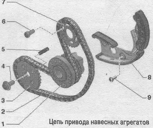
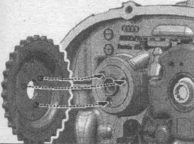
1. Crankshaft. 2. Power take-off drive chain: mark the direction of rotation for reverse installation. 3. Oil chain drive sprocket. pump; mounting position: the side with the marking faces the engine. 4. Bolt: replace: 30 Nm + tighten by 90°. 5. Pressure spring. 6. Bolt: replace; 15 Nm + turn 90° further. 7. Balance shaft sprocket; installation position: the side with the marking faces the gearbox. 8. Chain tensioner: with a guide bar. 9. Bolt: replace; 10 Nm + turn further by 45°.
Take off
The gearbox is removed. Remove the lower cover of the drive chains. Risk of damage to the drive chain due to threads that are too long. Only bolts with a thread length "a" of maximum 22 mm may be used to lock the wrench "T40049". If only bolts with a longer thread are available, place a washer under the bolt head to ensure a thread length of 22 mm.
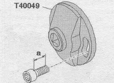
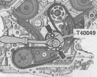
Install the "T40049" key onto the rear of the crankshaft using 2 "arrow" bolts.
Unscrew the threaded plug "arrow" for the "TDC" mark from the cylinder block. Turn the crankshaft in the direction of engine rotation to "TDC".
Screw the fixing bolt "T40069" into the hole with a torque of 20 Nm; if necessary, to completely center the bolt, slightly turn the crankshaft "1" in both directions.
Press the chain tensioner slider in the direction of the arrow and secure the chain tensioner with the T40071 locking pin. Risk of failure due to reverse rotation of an already used drive chain. For reassembly, mark the direction of the drive chain with an arrow, using paint for this. Do not make notches on the chain drive with a center punch or similar tools. Unscrew bolts "3" and remove the balance shaft sprocket. Unscrew bolts "1" and "2" and remove the chain tensioner together with the chain.
Install
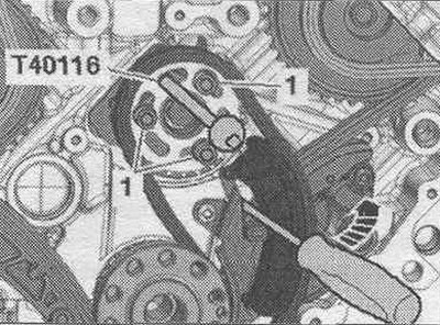
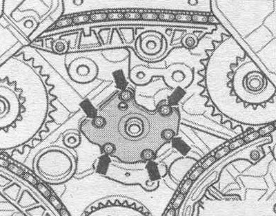
Crankshaft "1" is locked in the "TDC" position using the "T40069" locking screw. Install the chain tensioner with the chain and the balance shaft sprocket. Secure the balance shaft at TDC using the T40116 pin. The longitudinal holes in the balance shaft sprocket must be centered on the threaded holes in the balance shaft. If necessary, move the chain one tooth. Tighten the chain tensioner bolts. Loosely screw in sprocket bolts "1." The sprocket should rotate on the balance shaft but should not tilt sideways. To unlock the chain tensioner, remove pin "T40071." Use a screwdriver to press the chain guide bar "arrow" while simultaneously tightening the sprocket bolts "1." Remove pin "T40116" from the balance shaft.
Installation in reverse order. Install the lower drive chain cover. Screw in the threaded plug for the TDC mark on the crankshaft.
Balance shaft
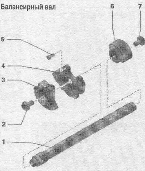
1. Balance shaft. 2. Bolt: 60 Nm; to loosen and tighten, use pin "T40116" as a counter support. 3. Counterweight on the gearbox side: is installed on the balance shaft in only one position. 4. Support body. 5. Bolt: 13 Nm. 6. Balance shaft on the belt pulley side: installed on the balance shaft in only one position. 7. Bolt: 60 Nm; to loosen and tighten, use pin "T40116" as a counter support.
Removal and installation the balance shaft
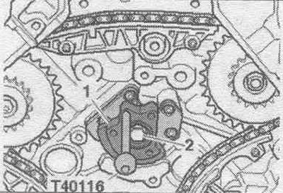
The gearbox is removed. Remove the seal. flange on the belt pulley side. Remove the lower timing chain cover. Remove the auxiliary chain drive. units. Lock counterweight "1" at the rear of the engine using pin "T40116". Unscrew bolt "2" and remove the counterweight from the balance shaft.
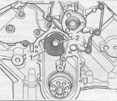
Unscrew bolt "2", holding the counterweight with a punch, and remove the front counterweight "1" on the engine from the balance shaft.
Loosen the arrow bolts and remove the balance shaft support shield. Remove the balance shaft from the cylinder block back.
Install
Crankshaft "1" is fixed in the "TDC" position using the "T40069" locking screw. Installation is in the reverse order. Counterweights are installed on the balance shaft in only one position. Install auxiliary chain drive. units. Install the lower cover of the drive chains. Install the seal. flange on the belt pulley side.