



Table of contents: Engine installation ↓ Support of units ↓ Removal and installation the left… ↓ Removal and installation the right… ↓
Engine installation
Tightening torques (Nm)
| Bolts and nuts | M6 | 9 |
| M7 | 15 | |
| M8 | 20 | |
| M10 | 40 | |
| M12 | 65 |
Ground bolt to the body near the shock absorber cup
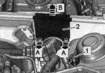
Tighten ground bolt "1" to 9 Nm.
Ground wires to the side members
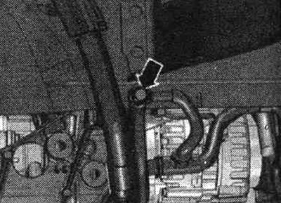
Tighten the arrow nut to a torque of 9 Nm.
Engine to DSG 0B5 gearbox
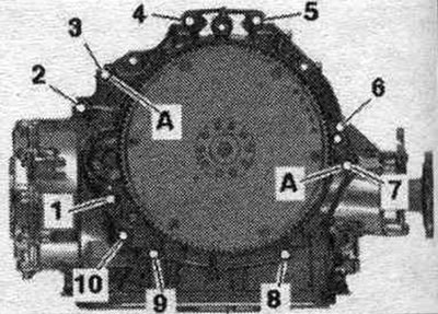
| Pos. | Bolt | Nm |
| 1 | M10x50(1) | 65 |
| 2...6 | M12x100 (2) | 30 + 90° |
| 7 | M12x125(2) | 30 + 90° |
| 8 | M10x60(2) | 15 + 90° |
| 9,10 | M10x95 (2) | 15 + 90° |
| A | Centering bushings | |
(1) The bolt strength class is 10.9, the steel bolt can be used repeatedly.
(2) Aluminum bolts can be used twice.
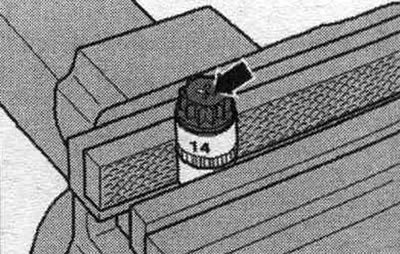
Aluminum bolts "2...10" can be used no more than twice. Therefore, after the first use, mark these bolts with two "X" or "arrow" notches. To avoid damaging the bolts during notching, do not clamp them in a vice. Insert the bolt as shown in the illustration into the 14 mm socket using a 1/2-inch drive, which can then be clamped in a vice. Bolts marked with "X" must not be reused.
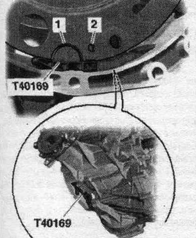
Replace bolts that were tightened with additional tightening. Replace self-locking nuts, lip seals, gaskets and seals. rings. On vehicles with a dual-clutch transmission 0B5, a needle bearing is installed in the driven disk. Before dismantling, make sure the needle bearing is installed. Pressing in and pressing out a needle bearing from a driven disk. Hose fittings, air tubes and hoses must be cleaned of oil and grease before installation. To secure all hose connections, use clamps of the appropriate series. To ensure reliable fastening of the air duct hoses to the fittings, all cable ties should be placed in their original locations during installation. Install the engine mounts and engine cushion. When installing the engine on the subframe, hold the ATF lines in the mounting position. Before assembling the gearbox, be sure to clean the threaded holes in the cylinder block where the engine mounts to the gearbox using a tap. Before connecting the engine and gearbox, perform the following preparatory steps: Insert the mounting device "T40169" from below into the gearbox housing and install the clutch module as shown in the figure. The mounting fixture should fit into the semicircular groove "1" and additionally into the inspection hole "2." To locate the inspection hole, it is necessary to rotate the clutch module.
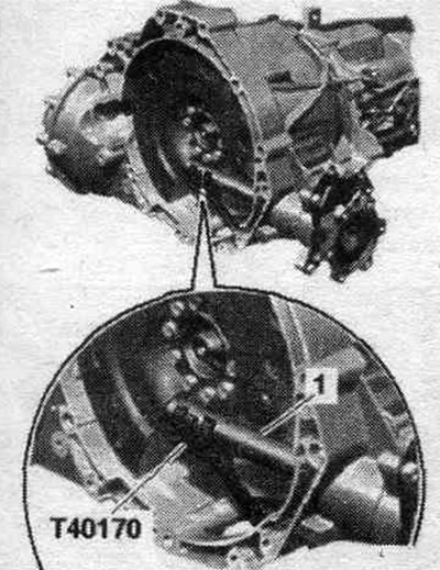
Insert the mounting fixture bolts into the hole in the gearbox housing. Insert the "T40170" transport fastener into the clutch module housing from below, then secure it to the shaft with flange "1.".
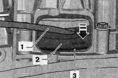
Check the presence of centering bushings "A" for the engine and gearbox in the cylinder block; insert the bushings if necessary. Check the aluminum engine-to-gearbox bolts for reuse and mark them if necessary. Install the gearbox onto the engine and tighten bolts "1, 6...10." Remove transport bracket "T40170" and mounting fixture "T40169." This step ensures that the clutch module fits evenly on the driven disc and does not warp. Press the clutch module "2" using the mounting lever "1" to the driven disk "3" "arrow".
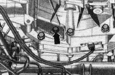
Secure the clutch module to the driven disc as follows. To tighten the bolts use a ring spanner SW 16 "VAG 1332/14". Screw in the first "arrow" bolt by hand (2 Nm).
Insert the guide pins of the adapter "T40058" as shown below: the large diameter "arrow 1" faces the engine, the small diameter "arrow 2" faces the adapter. Turn the crankshaft with adapter -T40058; and with a 180° offset open-end wrench in the direction of engine rotation "arrow". In this crankshaft position, tighten the accessible bolt to the specified torque. Turn the crankshaft 60° and tighten the remaining 5 bolts to the specified tightening torque.

Install power steering lines. Install the system circulation pump. "V50" cooling system. Install the ATF lines. Bolt the left and right drive shafts to the axle shafts with the transmission flanges. Install the catalytic converters. First, raise the powertrain using the VAS 6131A lift until the gap between the subframe and the body is at least 100 mm.
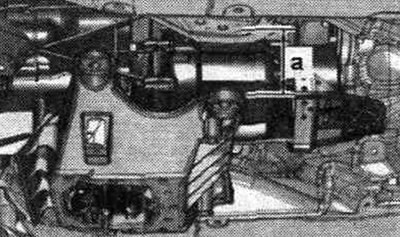
Install the selector cable and adjust if necessary. Raise the powertrain using the VAS 6131 A lift. Position the subframe and gearbox bracket according to the markings made on the side members during dismantling. Tighten the subframe bolts only with a light torque, do not tighten at an angle (tighten the bolts only after checking the wheel alignment angles).
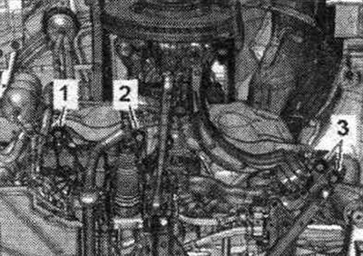
Tighten the tunnel crossmember arrow bolts. Installation in reverse order. Tighten the intermediate shaft onto the steering gear. Install the cardan shaft. Install the front muffler. Align the system. exhaust gas discharge without mechanical stress. Install the front cross member. Install the crosspiece for the subframe, upper arms and stabilizer, screw the shock absorber strut to the support arm on the left and right sides. Install diagonal bars. Install brake. support. Install the engine control unit. Electrical connections and wiring. Install the wires, the 2-way splitter 30 "TV22" and the cover of the motor junction box. compartment. Install the stretcher. Install the washer reservoir filler neck. Install refrigerant lines. Consider the steps to be taken after connecting the battery. Risk of damage to control units due to overvoltage. Do not use a battery charger to start the engine! Install fuel. discharge hose and air housing. filters. Install the radiator frame spacers. Fill with oil and check its level. Before starting the engine, pour hydraulic oil into the power steering expansion tank. The vane pump must not run dry. Connect the coolant hose to the nipple connector. Fill with coolant.
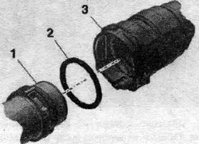
Fill the air conditioning circuit.
Install wheel arches. Install the front wheels. Perform a RUUK. Fill with ATF. Install noise insulation screens.
Support of units
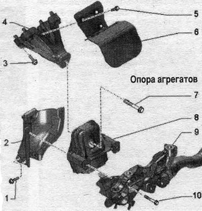
1. Bolt: 20 Nm. 2. Mounting plate: for engine mount; if the engine mount is defective, replace the mounting shield; check the mounting shield on the opposite side and replace if necessary. 3. Bolt: 40 Nm. 4. Engine support. 5. Bolt: 10 Nm. 6. Thermal insulation. 7. Bolt: replace; 90 Nm + turn further by 90°. 8. Engine mount: replace in pairs. 9. Subframe. 10. Bolt: 55 Nm.
Removal and installation the left engine mount
Note: To avoid repeat repairs if the engine mount is faulty, proceed as follows. Replace the defective engine mount and the corresponding mounting shield. Replace the engine mount on the opposite side, check the corresponding mounting shield, and replace it if necessary. Remove noise insulation shields "1" and "2." Install an oil suction and collection device under the engine. Unscrew the bolts "arrows" and secure the engine oil radiator with the coolant hoses "1" and "2" connected to the side.
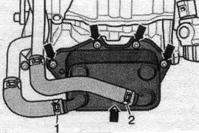
Vehicles with coolant recovery pump "V51": Remove coolant recovery pump "V51".
All
Remove the compressor.
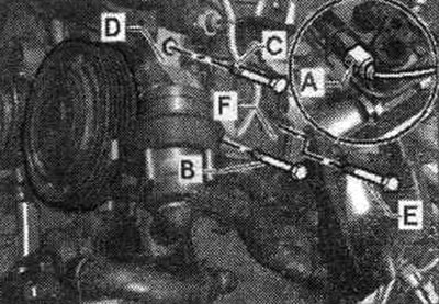
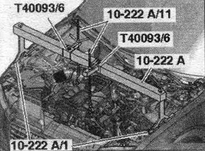
Install the "10-222 A" crossmember with the "T40093/6" adapters on the upper shock absorber support on the left and right, as shown in the figure. Hang the lead screws "10-222 A/11" to the left and right engine lugs. Apply pre-tension using the lead screws.
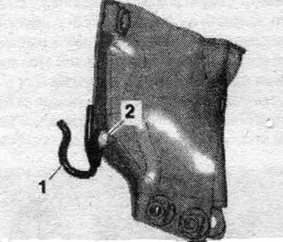
A/m with hydraulics. power steering: Unscrew nut "2" and release bracket "1".
All
Unscrew the left bolt "2" of the subframe. Do not unscrew the left bolts "1" and "3" and all the right subframe bolts.
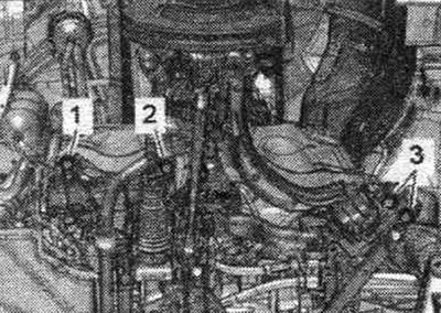
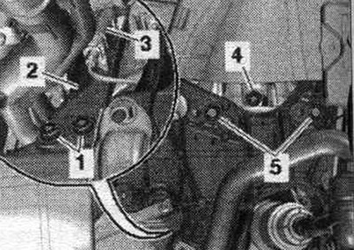
Disconnect the plug connector "3" of the left el. solenoid valve of the electrohydraulic engine mount "N144". Unscrew bolts "1, 4, 5" of the left engine mount. Set aside the mounting plate "2" of the left engine mount. Remove the left engine mount.
Install
Installation in reverse order. Bolts tightened at the tightening angle should be replaced. Tighten the subframe bolts. Install the compressor. Install the engine oil cooler. Install noise insulation screens.
Removal and installation the right engine mount
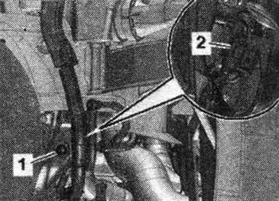
Install the "10-222 A" crossmember with the "T40093/6" adapters on the upper shock absorber support on the left and right, as shown in the figure. Hang the lead screws "10-222 A/11" to the left and right engine lugs. Apply pre-tension using the lead screws. Remove the right front wheel. Remove the front right fender liner. Remove noise insulation shields "1" and "2". Remove plug connector "2" of the solenoid valve of the right electrohydraulic engine mount "N145" from the bracket and disconnect the connector. Unscrew nut "1" and remove the wiring harness bracket from the subframe.
Unscrew bolts "1, 2, 4" and put aside the mounting plate "3" of the right engine mount.
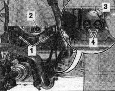
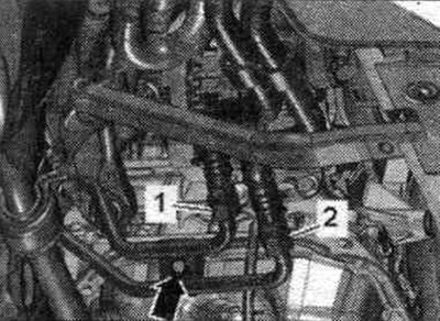
Cars with dual clutch transmission 0B5: Unscrew the "arrow" bolt from the ATF line fastening. "Pos. 1, 2" do not take into account.
All
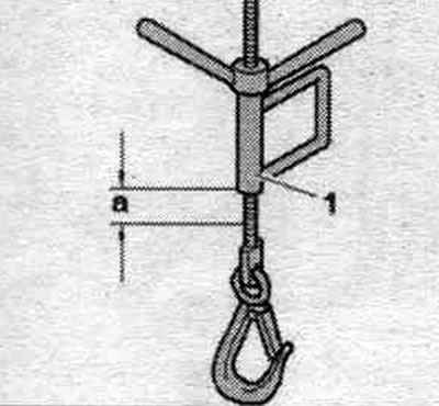
Raise the engine using the lead screw "10-222 A/11" "pos. 1" by dimension "a". Distance "a" = approx. 20 mm. Remove the right engine mount.
Install
Installation in reverse order. Bolts tightened at the tightening angle should be replaced.
Vehicles with dual clutch transmission 0B5: Install ATE lines.
All
Install the front fender liner and sound insulation. Install the front wheel.
The original article is available on the online resource: Audimanual.ru