Repair Chevrolet Repair Toyota Repair Honda Repair AvtoVAZ Repair Mercedes-Benz Repair BMW Repair Opel
Home  |  Contacts  |  Sitemap  |    
English Русский
Български
Беларускі
Український
Српски
Hrvatski
Română
Polski
Slovenský
Magyar
AudiManual.ru


  • AUDI 80
  • AUDI 100
  • AUDI A3
  • AUDI A4
  • AUDI A6
  • AUDI A8
  • AUDI Q
  • OTHER
  • ARTICLES
B8 (2007-2015) B7 (2004-2008) B6 (2000-2006) B6 (2000-2006, petrol) B5 (1994-2001) B5 (1994-2001, petrol)

Valve mechanism — removal and installation (Audi A4 B8)

  • Home
  • Audi A4
  • B8 (2007-2015)
  • Power unit
  • Petrol engines 3.0 l
  • Valve mechanism — removal and installation
            0
Caution! Risk of damage to valves and piston crowns after working on the valve train. Since the hydraulic lifters must be settled, after installing the camshafts the engine should not be run for approx. 30 min. To ensure that no valves are in contact with the cylinder head during operation, carefully rotate the engine at least 2 revolutions. Cylinder heads with cracks between the valve seats or between the valve seat ring and the spark plug seat threads can be used without reducing service life, provided the cracks are small, no wider than 0.3 mm, or if they affect only the first 4 threads of the spark plug seat threads.


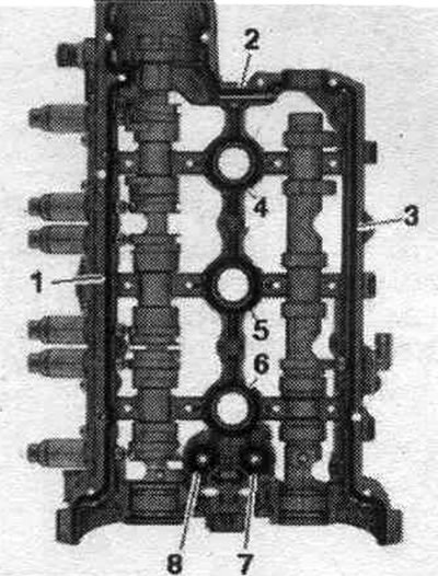
The figure shows the cylinder head of cylinder bank 2 (left).

1. Plug: Install with sealant. 2. Cylinder head. 3. Oil seal. 4. Valve spring. 5. Hydraulic…

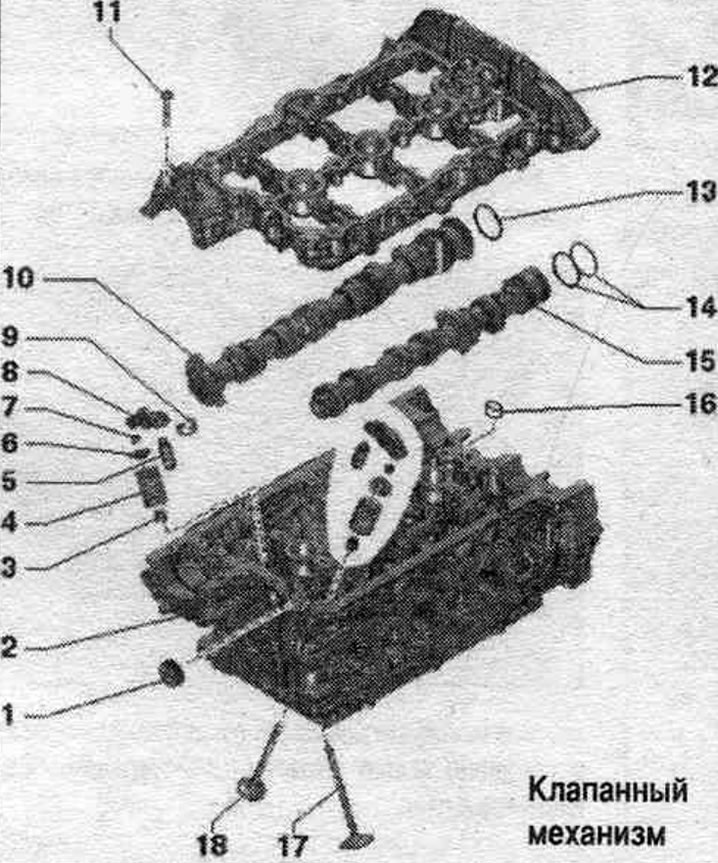
1. Plug: Install with sealant. 2. Cylinder head. 3. Oil seal. 4. Valve spring. 5. Hydraulic compensator: fixed in the roller lever "pos. 8"; mark mont. reinstallation position: lubricate the working surfaces before installation. 6. Valve spring plate. 7. Valve cracker. 8. Rocker arm: mark installation. reinstallation position: Check the roller bearing for ease of movement: Lubricate the working surfaces before installation; for installation, secure with the safety clamp "pos. 9" on the hydraulic compensator "pos. 5". 9. Locking clamp: not supplied separately, check the reliability of the fastening. 10. Intake camshaft; maximum runout: 0.04 mm. 11. Bolt: replace. 12. Camshaft frame: with integrated camshaft bearings. 13/14. Rectangular section ring. 15. Exhaust camshaft; maximum runout: 0.04 mm. 16. Mesh oil filter. 17. Inlet valve: cannot be machined, only lapping is allowed; mark mont. reinstallation position. 18. Exhaust valve: cannot be machined, only lapping is allowed; mark mont. reinstallation position.


Mounting position of the valve spring


The frequent turns of the «arrow» spring face the cylinder head.

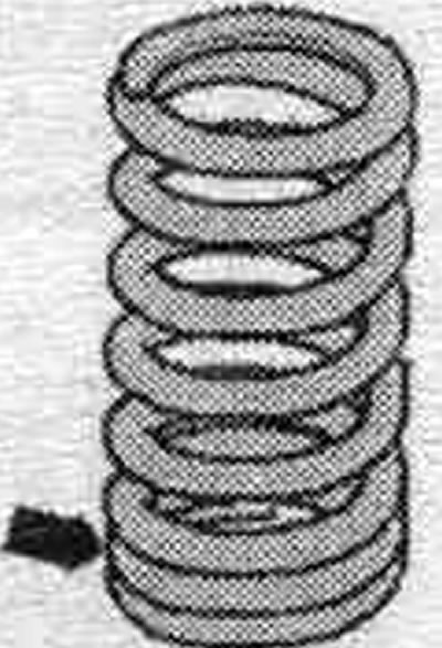
The frequent turns of the "arrow" spring face the cylinder head.


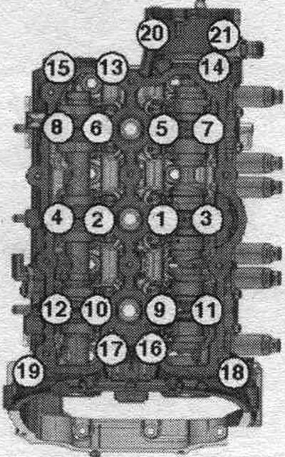
Camshaft frame - last and tightening torque


The camshaft frame for the left cylinder head is shown. On the right cylinder head, the steps are performed in a mirror image. Bolts tightened at the tightening angle should be replaced. Tighten the bolts in 3 stages in the sequence shown.
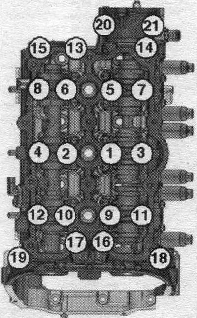
The camshaft frame for the left cylinder head is shown. On the right cylinder head, the steps are…


StepBoltsTightening torque/rotation angle
1"1...21"Tighten the bolts by hand until they stop
The frame must fit snugly against the cylinder head over the entire mating surface
2"1...21"8 Nm
3"1...21"Turn 90° further

Removal and installation camshafts


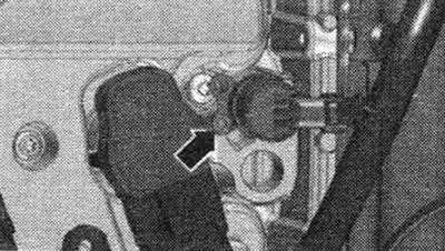
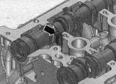
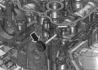
Remove the chains from the camshafts. To remove the camshafts from the left cylinder head, remove the vacuum pump. To remove the camshafts from the right cylinder head, remove the high-pressure pump and the high-pressure pump drive housing. Unscrew the "arrow" bolt and remove the system valve. regulation of the timing phases.


Remove the chains from the camshafts. To remove the camshafts from the left cylinder head, remove…


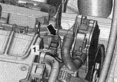
Disconnect connector "1" on the Hall sensor. Ignore the "arrow.". Loosen the camshaft frame bolts in sequence. "21...1". For the right camshaft frame, the steps are performed in mirror order. Remove the bolts, carefully remove the glued camshaft frame and place it on a soft pad on the workbench.

Disconnect connector «1» on the Hall sensor. Ignore the «arrow.». Loosen the camshaft frame bolts…


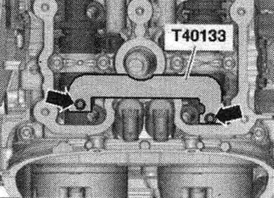
Remove the camshaft retainer "T40133" "arrows". Mark and remove the camshafts.

Remove the camshaft retainer «T40133» «arrows». Mark and remove the camshafts.


Install


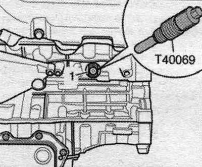
Replace gaskets and plugs. Crankshaft "1" is locked in the "TDC" position using the "T40069" locking screw. The hydraulic lifters and rocker arms are installed.


Replace gaskets and plugs. Crankshaft «1» is locked in the «TDC» position using the «T40069»…


Remove any remaining sealant from the cylinder head and camshaft frame, for example, with a rotating brush attachment with plastic bristles. Clean the sealing surfaces from oil and grease. Check the "arrow" mesh for contamination and clean it if necessary. Lubricate the working surface of the camshafts with oil.

Remove any remaining sealant from the cylinder head and camshaft frame, for example, with a…


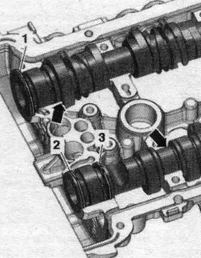
Place the camshafts into the frame. The camshafts must lie precisely in the axial bearings of the frame's "arrows." The joints of the rectangular rings "1, 2, 3" must be facing up or down. The joints of rectangular cross-section rings must not under any circumstances be facing sideways. Rotate the camshaft frame with the camshafts inserted, while holding the camshafts in the frame.

Place the camshafts into the frame. The camshafts must lie precisely in the axial bearings of the…


Turn the camshafts until the threaded holes with the arrows facing upwards. Check that the camshafts are positioned correctly in the frame axle bearings.


Turn the camshafts until the threaded holes with the arrows facing upwards. Check that the…


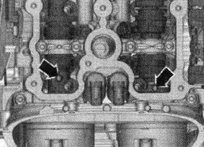
Install the camshaft retainers "T40133" on both cylinder heads and tighten to 25 Nm "arrows". Observe the sealant shelf life. Cut off the tube tip along the front mark (opening diameter approx. 2 mm). Turn the camshaft frame again. Danger of contamination of system channels. lubrication when there is excess sealant. The sealant beads must not be thicker than the specified size. Apply a bead of sealant "4...8" to the clean seating surfaces of the camshaft frame, as shown in the figure. Sealant bead thickness: 2.0 mm. Apply a bead of sealant "1...3" to the clean camshaft frame mounting surfaces, as shown in the figure. Sealant bead thickness: 2.5 mm. Install the camshaft frame within 5 minutes after applying the sealant.

Install the camshaft retainers «T40133» on both cylinder heads and tighten to 25 Nm «arrows».…


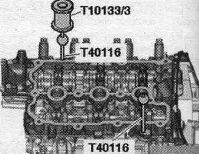
Place the camshaft frame on the cylinder head. Insert the "T40116" retaining pins into the frame and cylinder head.


Place the camshaft frame on the cylinder head. Insert the «T40116» retaining pins into the frame…


Tighten the camshaft frame mounting bolts. After installing the crankshaft frame, allow the sealant to cure for about 30 minutes. Clean the cylinder head plug hole of oil and grease. Apply sealant around the outer perimeter of the arrowhead plug. Install the plug flush.

Tighten the camshaft frame mounting bolts. After installing the crankshaft frame, allow the sealant…


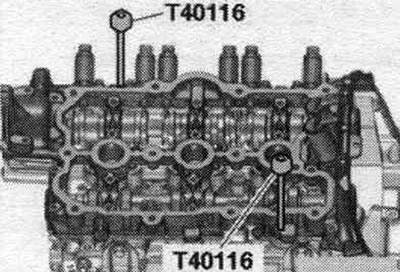
Remove the "T40116" retaining pins with the "T10133/3" slide hammer.

Remove the «T40116» retaining pins with the «T10133/3» slide hammer.


Installation in reverse order. Install the high pressure pump and the high pressure pump drive housing. Install a vacuum pump. Install the drive chains on the camshafts. Risk of damage to valves and piston crowns after working with the valve mechanism. Since the hydraulic lifters must be settled, after installing the camshafts the engine should not be started for approx. 30 min. To ensure that no valves come into contact with the cylinder head during operation, carefully crank the engine at least 2 revolutions.

Installation in reverse order. Install the high pressure pump and the high pressure pump drive…
The article was checked by auto expert Timur Bazhenov
This article is available at russian, bulgarian, belarusian, ukrainian, serbian, croatian, romanian, polish, slovak, hungarian

Share information:
Previous articles
Audi A4 B8: Petrol engines 3.0 l
Next articles

Cylinder head (CH) — removal and installation
Chain drive
Cylinder block from the gearbox side
Cylinder block from the belt pulley side
Lubrication system — removal and installation
Cooling system — replacement of components
Compressor and intercooler
Fuel injection system — component layout


Similar articles on other Audi car models:
Removal, installation, testing of cold start valve (K-,… Audi 80 B3 (1986-1991)
Timing Belt and Sprocket Tensioner Mechanism — Removal and… Audi 100 C3 (1982-1990, diesel)
Removal and installation the locking mechanism Audi A3 Type 8L (1996-2003)
Removal and installation valve injectors Audi A6 C4 (1994-1997)
Removal and installation the engine Audi A8 D2 (1994-2002)
Removal and installation the mechanism and chain for the… Audi Q7 Typ 4L (2005-2015, diesel)
Removal and installation the EGR valve Audi A2 (1999-2005)
Link to this page in different formats


Visitor comments

No comments yet


How much will 22 + 30 =


A4(B8, 2007-2015) 
  • General information
  • Operating instructions
  • Power unit
  • Petrol engines 1.8 l
  • Petrol engines 1.8/2.0 l
  • Petrol engines 3.0 l
  • Petrol engines 3.2 l
  • Fuel system (petrol)
  • Diesel engines 2.0 l (CA*)
  • Diesel engines 2.0 l (CJCB)
  • Diesel engines 2.7/3.0 l
  • Diesel engines 3.0 l
  • Fuel system (diesel)
  • Transmission
  • Manual gearbox 0B1
  • Manual gearbox 0B2
  • Manual gearbox 0B3
  • Manual gearbox 0B4
  • Automatic transmission 0B5
  • Automatic transmission 0B6
  • Automatic transmission 0AW
  • All-wheel drive system
  • Chassis
  • Front suspension
  • Rear suspension
  • Brake system
  • Steering system
  • Body
  • Exterior
  • Interior
  • Seats
  • Doors, locks and windows
  • Security system
  • Heating and air conditioning
  • Electrical equipment
  • Audio system
  • Power devices
  • Equipment and devices
  • Lighting and lamps
  • Electrical circuits
 
A4(B7, 2004-2008) 
  • General information
  • Introduction to manual
  • Troubleshooting
  • Operating instructions
  • Maintenance
  • Power unit
  • Petrol engines 2.0 (ALT)
  • Petrol engines 2.0 (TFSI)
  • Petrol engines 1.8 (MPI)
  • Diesel engines
  • Cooling system
  • Air conditioner
  • Fuel and exhaust system
  • Ignition system
  • Starting and charging
  • Transmission
  • Clutch
  • Manual gearbox
  • Automatic gearbox
  • Drive shafts
  • Chassis
  • Brake system
  • Front suspension
  • Rear suspension
  • Steering
  • Body
  • Exterior
  • Interior
  • Electrical equipment
  • Equipment and devices
  • Lighting and signaling
  • Windscreen wipers and washers
  • Electrical diagrams
  • Electrical diagrams (since 2007)
 
A4(B6, 2000-2006) 
  • General information
  • Vehicle Description
  • User manual
  • Maintenance
  • Power unit
  • Gasoline engine
  • Diesel engine
  • Lubrication system
  • Cooling system
  • Supply system
  • Injection system
  • Exhaust system
  • Ignition and control
  • Transmission
  • Gear box
  • Clutch and drive shafts
  • Chassis
  • Brake system
  • Car suspension
  • Steering
  • Body
  • Heating and ventilation
  • Exterior (external elements)
  • Interior (internal elements)
  • Electrical equipment
  • Power devices
  • Lighting and appliances
  • Electrical circuits
 
A4(B6, 2000-2006, petrol) 
  • General information
  • Introduction to the guide
  • Car care
  • Power unit
  • Engine repair
  • Lubrication system
  • Cooling system
  • Injection and control system
  • Ignition system
  • Power and exhaust system
  • Transmission
  • Clutch and drive shafts
  • Car gearbox
  • Chassis
  • Suspension and wheels
  • Steering
  • Brake system
  • Body
  • Interior
  • Exterior
  • Electrical equipment
  • Equipment and devices
  • Lighting and signaling
  • Power devices
  • Electrical circuits
 
A4(B5, 1994-2001) 
  • General information
  • Introduction to the guide
  • Car care
  • Maintenance (gasoline)
  • Maintenance (diesel)
  • Power unit
  • Gasoline engines
  • Diesel engines
  • Engine overhaul
  • Cooling system
  • Fuel injection (gasoline)
  • Fuel system (diesel)
  • Exhaust system
  • Ignition system
  • Transmission
  • Clutch
  • Mechanical gearbox
  • Automatic gearbox
  • Drive shafts
  • Chassis
  • Brake system
  • Car suspension
  • Steering
  • Body
  • Exterior
  • Interior
  • Doors, locks and windows
  • Heating and ventilation
  • Electrical equipment
  • Power devices
  • Equipment and devices
  • Electrical circuits
 
A4(B5, 1994-2001, petrol) 
  • General information
  • Vehicle description
  • Maintenance
  • Power unit
  • Engine repair
  • Turbocharging
  • Exhaust system
  • Cooling system
  • Ignition system
  • Fuel system
  • Motronic injection system
  • MPI and MPFI injection system
  • Transmission
  • Clutch
  • Gearbox and shafts
  • Chassis
  • Steering
  • Car suspension
  • Brake system
  • Wheels and tires
  • Body
  • Heating and ventilation
  • Body parts
  • Electrical equipment
  • Fuses and relays
  • Power devices
  • Lighting and lamps
  • Tools and devices
  • Electrical circuits
 
AudiManual.ru © 2017-2026 · Mobile version · Feedback · Sitemap: EN BG BY UA RS HR RO PL SK HU · Site search · News and articles
80 B2 · 80 B3 petrol · 80 B3 · 80 B4 · 100 C3 diesel · 100 C3 petrol · 100 C3 · 100 C4 petrol · 100 C4 · A3 Type 8L · A4 B5 petrol · A4 B5 · A4 B6 petrol · A4 B6 · A4 B7 · A4 B8 · A6 C4 · A6 C5 · A6 C5 Allroad · A8 D2 · Q5 Type 8R · Q7 Typ 4L · Audi A2 ·
This site uses cookies 🍪. Click the button to accept this fact.