
Table of contents: Overview of installation locations ↓ Air filter ↓ Removal and installation the air… ↓ Lower part of the intake manifold ↓ High pressure pump ↓
Overview of installation locations
Right engine compartment
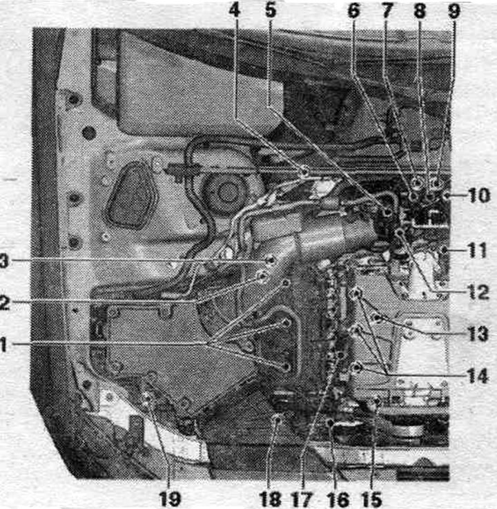
1. Ignition coils for cylinder bank 1: Coil 1 with power stage "N70". Coil 2 with power stage "N127". Coil 3 with power stage "N291". 2. Lambda probe "G39" with lambda probe heater "Z19": 55 Nm. 3. Timing phase adjustment valve 1 "N205". 4. Lambda probe after catalytic converter "G130" with lambda probe 1 heater element after catalytic converter "Z29": 55 Nm. 5-6. Secondary air injection valve "N112". 7. Intake air temperature sensor "642"/intake manifold pressure sensor "G71". 8. Intake manifold flap valve "N316". 9. Solenoid. Activated carbon filter valve 1 "N80". 10. Secondary air supply control valve 2 "N320". 11. Regulating valve control unit "J808": After replacing the throttle valve module "J808", perform the Adaptation function in the Guided functions mode. 12. Throttle control unit "J338": After replacing the throttle control unit "J338", perform the Adaptation function in the Guided functions mode. 13. Knock sensor 1 "G61". 14. Injectors, cylinder bank 1: Injector cyl. 1 "N30". Cyl. injector. 2 "N31". Cyl. injector. 3 "N32". 15. Intake manifold flap potentiometer "G336". 16. Hall sensor "G40". 17. Boost pressure sensor "G31" intake manifold temperature sensor "G72". 18. High-pressure pump; with fuel metering valve "N290", with low-pressure circuit fuel pressure sensor "G410". 19. Secondary air pump electric motor "V101".
In the engine compartment on the left
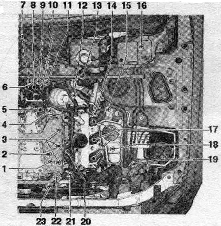
1. Fuel pressure sensor "G247": 22 Nm; lubricate the threads. 2. Knock sensor 2 "G66". 3. Injectors, cylinder bank 2: Injector cyl. 4 "N33". Cyl. injector. 5 "N83". Cyl. injector. 6 "N84". 4. Oil pressure sensor for low pressure "F378". 5. Throttle valve control unit "J808": after replacing the throttle valve module "J808", perform the Adaptation function in the Guided functions mode. 6. Secondary air injection valve "N112". 7. Intake air temperature sensor "G42" / intake manifold pressure sensor "G71". 8. Intake manifold flap valve "N316". 9. Solenoid valve 1. activated charcoal canister "N80". 10. Secondary air injection valve 2 "N320". 11. Oil pressure sensor "F22". 12. Engine speed sensor "G28": 9 Nm. 13. Lambda probe 2 after catalytic converter "G131" with lambda probe 2 heater after catalytic converter "Z30": 55 Nm. 14. Timing phase adjustment valve 2 "N208". 15. Lambda probe 2 "G108" with lambda probe 2 heating element "Z28": 55 Nm. 16. Engine control unit "J623": after replacement, perform adaptation in the "Geführte Funktionen" mode (Slave functions). 17. Coils, bank 2: Coil 4 with output stage "N292". Coil 5 with output stage "N323". Coil 6 with output stage "N324". 18. Oil pressure regulating valve "N428". 19. After-run coolant pump "V51": not installed on all trim levels or export versions. 20. Intake manifold temperature sensor 2 "C430" Boost pressure sensor 2 "G447". 21. Hall effect sensor 2 "G163". 22. Intake Manifold Flap Potentiometer 2 "G512": After replacement, perform an adaptation in the "Adaptive Functions" mode (Slave functions). 23. Coolant temperature sensor "G62".
Verification data
| Idle speed | It is not manually adjustable; adjustment is made by stabilizing the idle speed |
| Fuel pressure before the high pressure pump | 3.0...6.0 bar excess pressure |
| Fuel pressure at the outlet of the high pressure pump | 30...125 bar excess pressure |
Installation location of the engine control unit "J623"
In the left switching unit of the motor. compartment.
Installation location of the accelerator pedal position sensor "G79"/accelerator pedal position sensor 2 "G185"
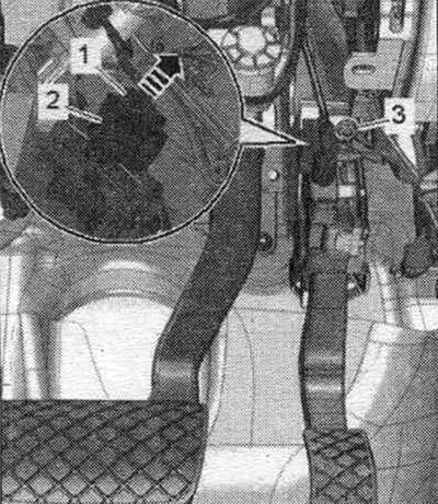
2. Plug connector. The accelerator pedal position sensor "G79" and the accelerator pedal position sensor 2 "G185" are integrated into the accelerator pedal module and cannot be replaced individually.
The pedal block contains the following elements:
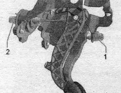
1. Brake light switch "P"/brake pedal sensor "F47". 2. Clutch pedal position sensor "G476" integrated functions: clutch pedal position sensor for engine starting "F194" and clutch pedal switch "F36". To ensure secure installation, the switch is installed only once.
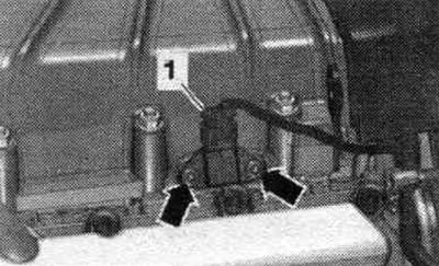
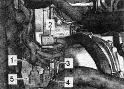
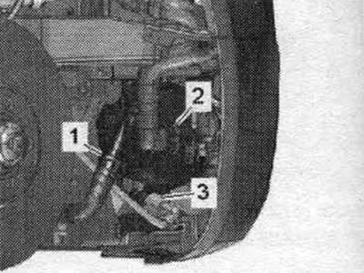
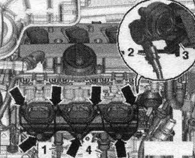
The following elements are located on the rear of the engine:
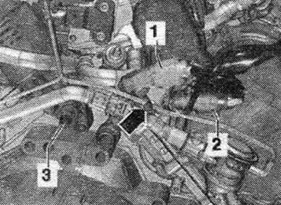
1. For knock sensor 1 "G61". 2. To the injectors of cylinder bank 1. 3. Oil pressure sensor "F22".
Plug connectors on the rear left side of the engine
1. To the injectors of cylinder bank 2 and to the fuel pressure sensor "G247". 2. For the knock sensor 2 "G66".
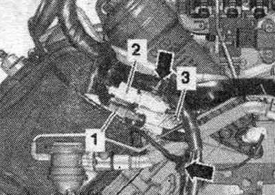
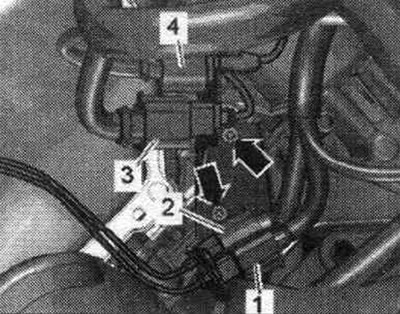
The following elements are located on the rear of the engine:
1. Secondary air supply valve "N112". 2. Intake manifold flap valve "N316". 3. Secondary air supply control valve 2 "N320". At the rear of the compressor with charge air cooler.
The following elements are located on the rear of the engine:
1. Intake air temperature sensor "C42"/intake manifold pressure sensor "G71". Located on the rear of the compressor with charge air cooler.
Connector of the electromagnetic valve 1 of the activated carbon tank "N80" "3"
Installation location of the throttle control unit "J338"
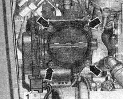
On the back of the compressor.
Installation location of the control unit for the regulating valve "J808"
3. Control unit for the regulating valve "J808". On the rear of the compressor.
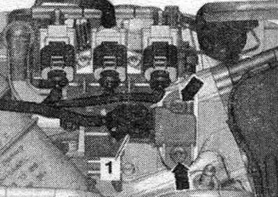
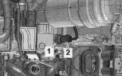
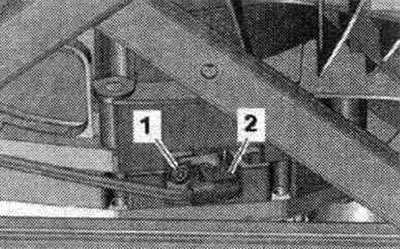
Hall sensor and valve timing control, cylinder bank 1 (right)
1. Valve 1 of the timing phase adjustment "N205". 2. Hall sensor "G40".
Hall sensor and valve timing control, 2nd row of cylinders (left)
1. Hall sensor 2 "G163". 3. Valve 2 for adjusting the timing phases "N208".
Mounting locations: under intake manifold, cylinder bank 1 (right)
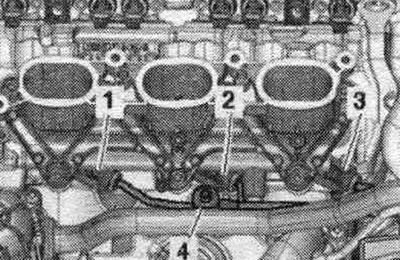
1. Injector cyl. 1 "N30". 2. Cyl. injector. 2 "N31". 3. Cyl. injector. 3 "N32". 4. Knock sensor 1 "G61".
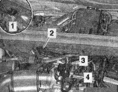
Mounting locations: under intake manifold, cylinder bank 2 (left)
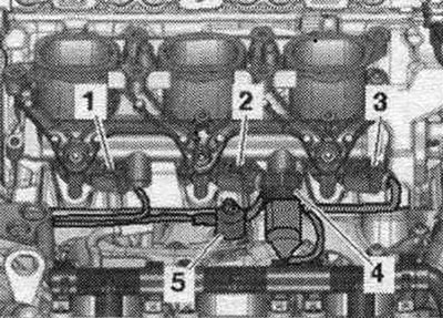
1. Injector cyl. 6 "N84". 2. Cyl. injector. 5 "N83". 3. Cyl. injector. 4 "N33". 4. Fuel pressure sensor "G247". 5. Knock sensor 2 "G66".
Low pressure oil pressure sensor "F378" "1"
Installation location of the oil pressure regulating valve "N428"
4. Oil pressure regulating valve "N428" On the left under the engine.
Installation location of the intake pipe flap motor 2 "G512"
On the front, on the lower part of the left intake manifold. The intake manifold flap potentiometer "G336" is located in a mirror image.
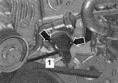
Installation location of the coolant temperature sensor "G62"
1. Coolant temperature sensor "G62" at the front of the engine.
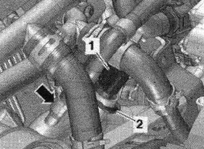
Installation locations on the fuel injection pump
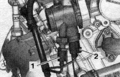
1. Low-pressure fuel pressure sensor "G410". 2. Fuel metering valve "N290". On the right side of the cylinder head.
Installation location of the engine speed sensor "G28"
Screwed to the gearbox body from below.
Installation location of the boost pressure sensor "G31"/intake manifold temperature sensor "G72"
On the right side of the compressor with the charge air cooler. Intake manifold temperature sensor 2 -64307, boost pressure sensor 2 "G447" are located in a mirror image.
Installation location of the left electromagnet of the electrohydraulic engine mount "N144" or the right electromagnet of the electrohydraulic engine mount "N145"
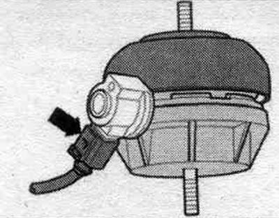
On the left and right engine mounts there is an arrow.
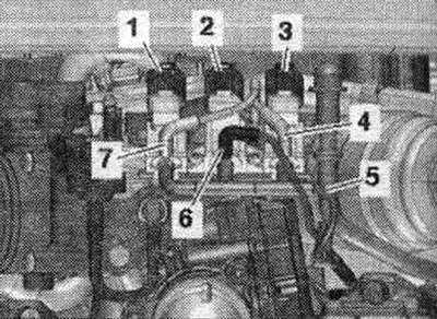
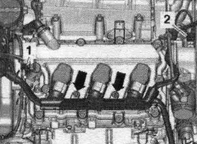
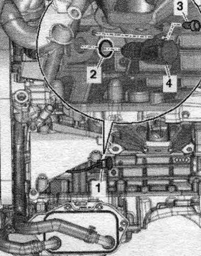
Lambda probe connectors (cylinder bank 1)
1. Injectors (cylinder row 1). 2. Throttle control unit "J338". 3. Knock sensor 1 "G61". 4. For lambda probe "G39" with lambda probe heater "Z19". 5. For lambda probe after catalytic converter "G130" with lambda probe heater 1 after catalytic converter "Z29".
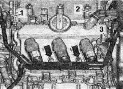
Lambda probe connectors (cylinder bank 2)
1. For lambda probe 2 after catalytic converter "G131" with lambda probe 2 heating after catalytic converter "Z30". 2. For lambda probe 2 "G108" with lambda probe 2 heating "Z28". 3. Injectors (cylinder bank 2) and for the fuel pressure sensor "G247". 4. For the knock sensor 2 "G66".
Location of lambda probes for the 1st cylinder bank (right)
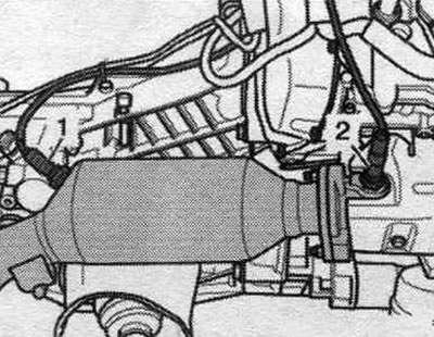
1. Lambda probe after catalytic converter "G130" with lambda probe heating element 1 after catalytic converter "Z29". 2. Lambda probe "G39" with lambda probe heating element "Z19".
Location of lambda probes for the 2nd row of cylinders (left)
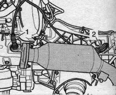
1. Lambda probe 2 "G108" with lambda probe 2 heating element "Z28". 2. Lambda probe 2 after catalytic converter "G131" with lambda probe 2 after catalytic converter heating "Z30".
Installation location of the secondary air pump electric motor "V101"
Under the right headlight.
Installation location of the pump for bleeding the coolant after turning off the engine "V51"
Front left on the engine. The coolant circulation pump -V51 - is installed on vehicles with certain configurations or for certain sales markets, only for countries with very hot climates.
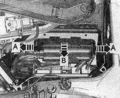
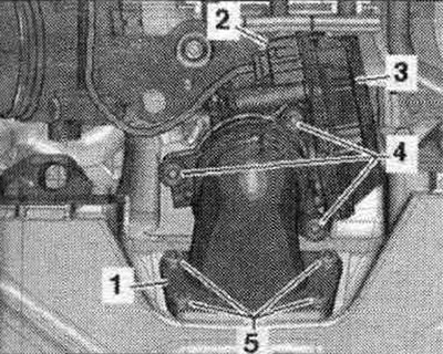
Air filter
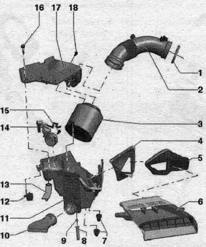
1. Hose clamp. 2. Air duct hose: to throttle control module "J338"; when installing, take into account the marking (the arrow points towards the throttle control unit bolt "J338"). 3. Replaceable air element. filter: Always use the original filter element; and also clean the fine filter (if installed). 4. Air duct: fixed at the top of the air duct. filter; clean the air duct from dirt and leaves. 5. Air duct: clean the air duct from dirt and leaves. 6. Air duct: to the radiator frame; clean the air duct from dirt and leaves. 7. Rubber tip. 8. Water drain hose: clean the water drain hose from dirt and leaves. 9. Water drainage hose guide. 10. Heated air supply line (only in countries with cold climates): Insert the heated air supply line into the air filter until it stops and turn it clockwise until it clicks. 11. Lower part of the air. filter: Clean the lower part of the air filter. filters from salt deposits, dirt and leaves; check the drain for dirt and clean if necessary. 12. Fastening for the lower part of the air. filter. 13. Secondary air pump suction hose: not installed on all vehicles. 14. Intake air switch valve "N335": not installed on all vehicles; the valve is installed but not used. 15. Bolt of intake air switching valve "N335". 16. Bolt. 17. Upper part of air. filters: Clean the top of the air filter. filters from salt deposits, dirt and leaves. 18. Bolt: for fastening the air liner. filter.
Removal and installation the air liner. filter
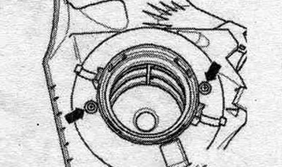
Remove the air duct hose from the air duct housing. filter by opening the "arrow" clamps.
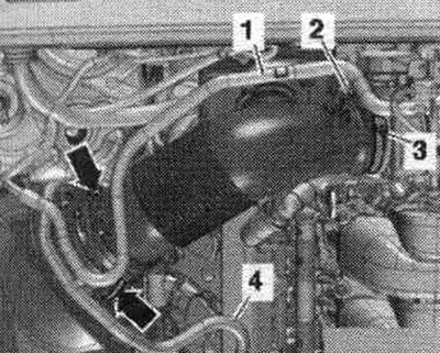
Unscrew the "arrow" bolts of the upper part of the air. filter and remove it upwards. Use only the original filter element. Use grease to install the air duct hose (silicone-free). Secure all hose connections with clamps of the appropriate series.
Check the condensate drain hose "arrow" at the bottom of the air duct. filters for dirt and clots (clean if necessary). Clean the air duct housing. filter (upper and lower parts) from residual salts, dirt or leaves (if necessary, clean by pumping out). Check the intake duct before the air intake element is replaced. filters for dirt. When installing a replacement air element. filter, make sure that it is in the center of the upper part of the air. filter.
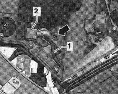
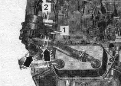
Bolt the new filter element to the top of the air filter. filter.
Connecting plate of air filter element. filter "1" must be adjacent to the connecting plate of the air duct housing. filter "2". Carefully, without applying much force, install the upper part of the air. filters to the bottom.
Before tightening the bolts, check again that the upper part is located in the groove of the lower part of the air. filter (air leakage through leaks). Screw the top part of the air. filter to the bottom. Ensure that the air duct hose is securely fastened. Installation in reverse order.
Lower part of the intake manifold
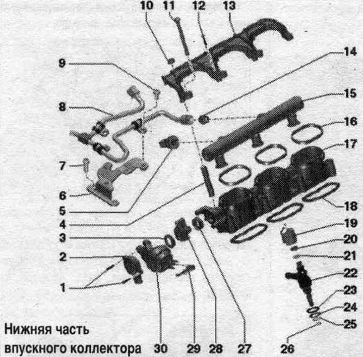
1. Screws: 2.5 Nm. 2. Intake manifold flap potentiometer; on the left is the intake manifold flap potentiometer 2 "G512", on the right is the intake manifold flap potentiometer "G336". 3. Lip seal: replace if damaged; to replace, lift it with a screwdriver and press it with your hand. 4. Bushing. 5. Fuel pressure sensor "G247": 22 Nm; lubricate the threads. 6. Bracket. 7. Bolt: 9 Nm. 8. High-pressure lines: relieve fuel pressure in the high-pressure circuit; connections must be free from damage; do not change the bent shape; for loosening and tightening fuel. hold the fittings on the main lines; before installing fuel. first tighten the fuel lines. highways; 27 Nm. 9. Bolt: 9 Nm. 10. Nut: 9 Nm. 11. Bolt: 9 Nm. 12. Bolt: 2.5 Nm. 13. Fuel locking bracket. ramps. 14. Threaded fitting: 40 Nm. 15. Fuel rail. 16. Gasket: Replace. 17. Lower Intake Manifold: When installing the lower intake manifold, the intake manifold flaps must be in the position that provides maximum power (the inlet channel is fully open). 18. Gasket: replace. 19. Support ring: check for proper fit; by means of a fuel spacer ring. the ramp creates a force that holds the injector in the cylinder head. 20. O-ring: replace, lubricate with clean oil. 21. Spacer ring: replace if damaged. 22. Injector. 23. Upper sealing washer. 24. Lower sealing washer. 25. Retaining ring. 26. Combustion chamber sealing ring. 27. Lip seal: replace if damaged; to replace, lift it with a screwdriver and press it with your hand. 28. Vacuum element drive lever. 29. Vacuum hose: to the intake manifold flap valve "N316". 30. Vacuum element of the intake manifold flap modules.
Lower Intake Manifold - Tightening Torque
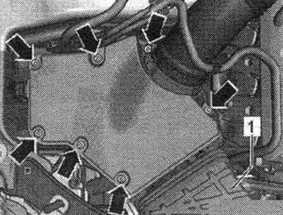
Tighten the bolts and nuts "arrows" of the lower part of the intake manifold crosswise in several steps. 10 Nm.
High pressure pump
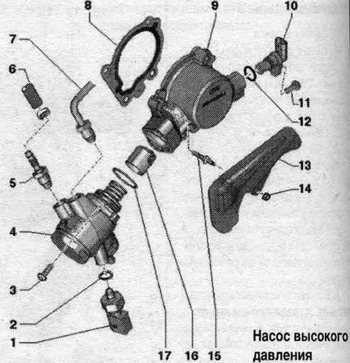
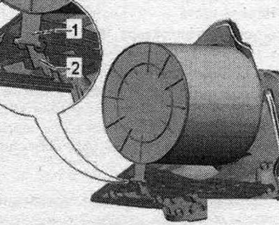
1. Low pressure fuel pressure sensor "G410": 15 Nm.
2. Lip seal: replace.
3. Bolt: tighten crosswise to 5 Nm; final torque 20 Nm; avoid distortion of the high pressure pump.
4. High pressure pump: with fuel metering valve "N290"; do not disassemble.
5. Threaded fitting: connections must be undamaged; 27 Nm.
6. Fuel supply. hose: low pressure circuit.
7. High-pressure fuel line: relieve fuel pressure in the high-pressure circuit; 27 Nm.
8. Gasket: replace.
9. Body.
10. Hall sensor "G40".
11. Bolt: 9 Nm.
12. O-ring: replace; before installation, wet with clean oil.
13. Protective screen of the high-pressure line.
14. Nut: 9 Nm.
15. Double bolt: 9 Nm.
16. Roller follower: installation is possible in only one position; before installation, wet with clean oil.
17. Sealing ring: replace; before installation, wet with clean oil.