
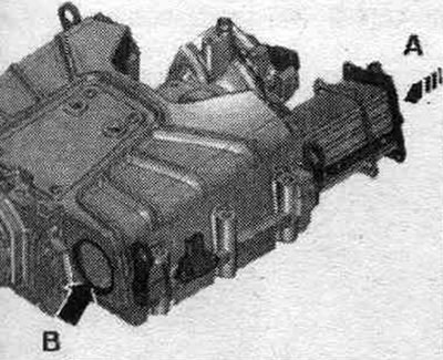
Compressor
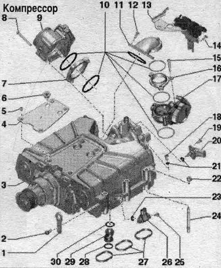
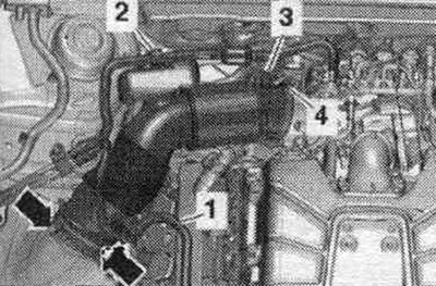
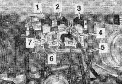
1. Engine suspension eye. 2. Bolt: 27 Nm. 3. Compressor: with intercoolers: for assembly work, secure on the tilting device "VAS 6095"; to check for leaks, attach to the "VAS 6095" tilting device. 4. Shock absorber plate. 5. Bolt: 5 Nm. 6. Rubber tip: 2 pcs. 7. Intermediate flange. 8. Bolt. 9. Throttle control unit "J338". 10. O-rings: replace. 11. Support. 12. Bolt. 13. Bracket: for changeover valves. 14. Bolt: 9 Nm. 15. Bolt. 16. Intermediate flange. 17. Control unit for the regulating flap "J808". 18. Air bleed screw of the left intercooler: 1.5...3.0 Nm. 19. Bolt. 20. Intake air temperature sensor "G42". 21. Sealing ring: replace. 22. Nut: 20 Nm. 23. Sealing ring: replace. 24. Grub screw: 17 Nm. 25. Bolt: self-locking; replace; before installation, be sure to clean the threaded holes with a tap; 10 Nm. 26. Boost pressure sensor: cylinder bank 1 (right) boost pressure sensor "G31", cylinder bank 2 (left) boost pressure sensor 2 "G447". 27. Gaskets: replace. 28. Sealing ring: replace. 29. Connecting pipe: engine crankcase ventilation. 30. Sealing ring: replace.
System control unit. vibration damper "J869" - tightening torque
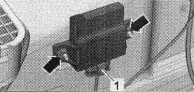
Tighten the arrow nuts to a torque of 5 Nm.
Actuating mechanism of the system. vibration suppression "R214" - tightening torque
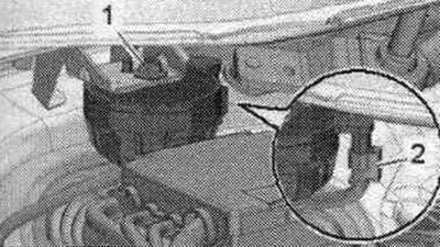
Tighten nut "1" to 5 Nm.
Take off
Remove the compressor poly V-belt. Place a service tray under the engine. Clamp the coolant hoses with clamps "3094" and disconnect them from the coolant pipes to the compressor by loosening the hose clamps. For better understanding of the montage. the position is shown with the engine removed. "Pos. 2" should not be taken into account.
Release fuel. hose "1" and hose "2" of the activated carbon absorber on the air duct. Remove vacuum hose "3" from the air duct connection. Remove the air duct hose by loosening the hose clamp "4" and opening the clamps "arrow".
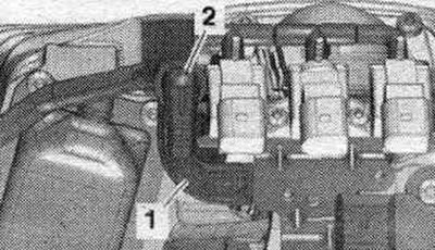
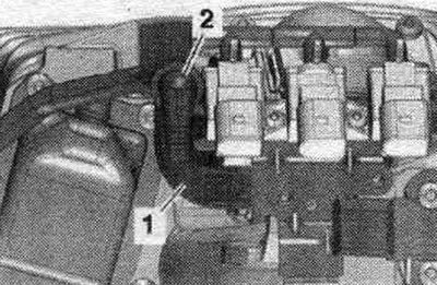
Disconnect the plug connector "3" of the electromagnetic valve 1 of the activated carbon absorber "N80" and remove the vacuum hose "4" by pressing on the locking tabs. Free up email. magnetic valve 1 of the activated carbon absorber "N80" from the bracket and together with the connected hose put aside. "Pos. 1, 2" do not take into account.
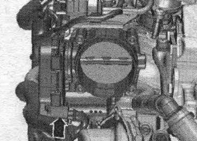
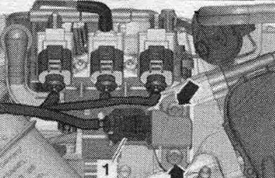
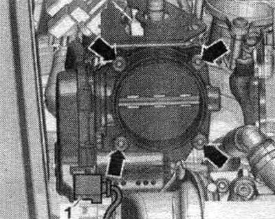
Disconnect the "arrow" connector from the throttle body module "J338".
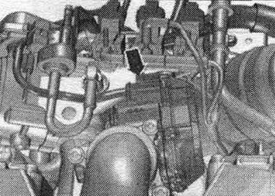
Disconnect the "arrow" connector from the regulating valve control unit "J808".
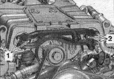
Disconnect plug connectors "1, 2, 3". Mark vacuum hoses for reinstallation. Remove vacuum hoses "4...7".
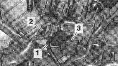
Disconnect plug "1" of the intake air temperature sensor "G42"/intake manifold pressure sensor "G71". Ignore the arrows.
Disconnect connector "3", if present, and remove vacuum hoses "1" and "2".
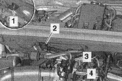
Release the vacuum hose "1". Unscrew the screws on the left and right of the "arrows" and remove the cover and bracket "2".
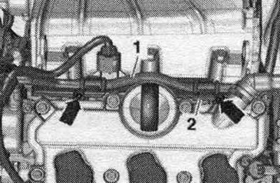
Release the vacuum hose "2" to the brake booster from the bracket "1".
Disconnect plug connectors "1" and "2". Loosen the nuts "arrows" and remove the compressor with intercoolers in an upward direction.
Close the openings on the compressor and on the boost air section with plugs from the VAS 6122 engine plug set. Remove the sound insulation.
Install
Installation in reverse order. Replace seals. Hose fittings, air tubes and hoses must be cleaned of oil and grease before installation. To secure all hose connections, use clamps of the appropriate series. To ensure reliable fastening of the air duct hoses to the fittings, the threaded connections of the already used clamps should be treated with a rust remover. When installing the compressor, ensure the correct mounting position of the system fitting. engine crankcase ventilation. Install the compressor poly V-belt. Fill with coolant.
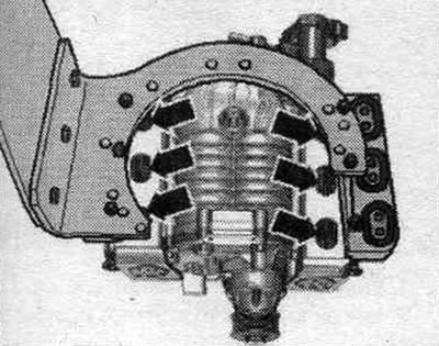
Intercooler
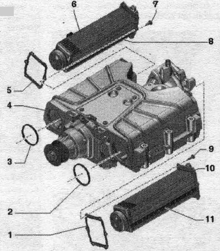
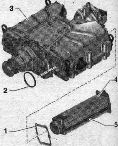
1. Gasket: replace. 2/3. O-ring: replace; when installing the intercooler, lubricate it with oil. 4. Compressor housing. 5. Gasket: replace. 6. Right intercooler. 7. Bolt: self-locking; replace; 10 Nm. 8. Gasket: not supplied separately; cannot be removed from the intercooler; when installing the intercooler, lubricate it with oil. 9. Bolt: self-locking; replace; 10 Nm. 10. Left intercooler. 11. Gasket: not supplied separately; cannot be removed from the intercooler; when installing the intercooler, lubricate it with oil.
Removal and installation the charge air cooler
The compressor for installation work is mounted on a bracket for the engine and gearbox "VAS 6095".
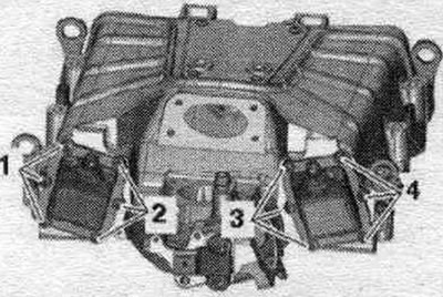
Left Intercooler: Disconnect bracket "1" of the vacuum hose. "Pos. 2" should not be taken into account. Remove the boost pressure sensor 2 "G447".
Right intercooler: Remove the throttle body "J338". Remove the boost pressure sensor "G31".
All
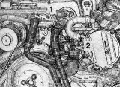
Unscrew bolts "1" and "2" and remove the coolant pipes to the compressor.
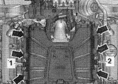
Unscrew bolts "1, 2" of the left intercooler and "3, 4" of the right intercooler.
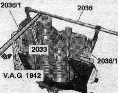
Attach the mounting device for valves "2036" with "2036/1" to the compressor as shown in the figure. Place the front tightening sleeve "2033" onto the intercooler. Slowly and with moderate pressure, press the intercooler out of the compressor housing using the "VAG 1942" tire mounting lever.
Install
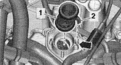
Replace gaskets, sealing rings and self-locking bolts. Before installation, be sure to clean the threaded holes in the compressor body with a tap. Check seal "5" on intercooler "4". The seal should not have any cracks or damage. Place seal "1" on the intercooler. Insert the seal. ring "2" into the hole in the compressor housing "3".
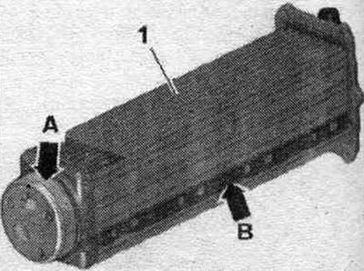
Lubricate the mounting surface "arrow A" and the seal "arrow B" of intercooler "1" with oil. Lubricate the inside of the compressor housing with oil as well.
When installing the intercooler, make sure that the seals of the recesses in the compressor housing are opposite each other "arrows".
To facilitate insertion and clamping of the intercooler, install the compressor housing vertically in the "VAS 6095" bracket. Insert the intercooler manually only. Insert the intercooler manually until it stops in the compressor housing "arrow A", while the front intercooler slides in the hole "arrow B" in the compressor housing.
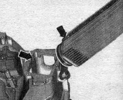
If necessary, manually guide the intercooler through the "arrow" holes in the compressor housing when inserting. As soon as the length of the bolts allows, screw in 2 bolts freely by hand for additional. intercooler input. The intercooler must not be tightened with mounting bolts. Insert the intercooler only by hand until its mounting flange with seal is seated with an indent of max. 1 mm to the compressor body. Only then tighten the bolts as described below.
Tighten bolts "1, 2" of the left intercooler and "3, 4" of the right intercooler in several stages, crosswise. Installation is in reverse order. Connect the coolant pipes to the compressor. Install the throttle module "J338". Check the compressor for leaks.
Drive head
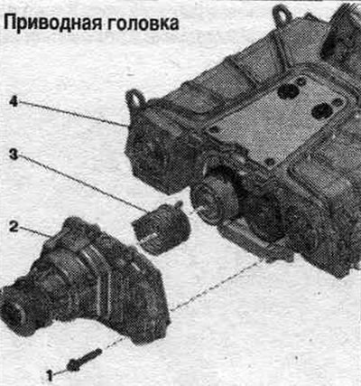
1. Bolt: self-locking; replace; before installation, be sure to clean the threaded holes with a tap; 25 Nm. 2. Drive head. 3. Spring. 4. Compressor housing.
(Text provided by the online resource: audimanual.ru)