
Table of contents: Hose connection diagram ↓ Draining and filling the coolant ↓ Cooling system pump, thermostat,… ↓ Removal and installation the water… ↓ Coolant supply pipes ↓ Coolant recovery pump "V51" ↓ Radiator system. cooling, front… ↓ Removal and installation the coolant… ↓
CAUTION! Risk of burns from hot steam and hot coolant. When the engine is warm, the cooling system is under excess pressure. To relieve excess pressure, place the expansion cap over the expansion tank. coolant reservoir with a rag and carefully open it. Risk of injury due to the radiator fan starting up by itself. Before starting work in the fan frame area, disconnect the plug connectors. To secure all hose connections, use clamps of the appropriate series. Arrows applied to the ends of the tubes and hoses of the system. cooling, must be located opposite each other.
Hose connection diagram
Note: Blue = large coolant circuit. Red = small coolant circuit. Orange = cooling circuit for intercooler. Brown = heating circuit. The arrows show the direction of coolant flow.
Cars without independent heater
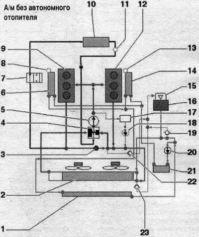
1. Front intercooler: Change coolant after replacement. 2. Coolant radiator; cars with DSG gearbox: with built-in ATF radiator; after replacement, change the coolant. 3. Coolant temperature sensor "G62". 4. Thermostat. 5. Water pump. 6. Right intercooler: in the compressor housing: after replacement, change the coolant. 7. Coolant supply shut-off valve: controlled by the Climatronic coolant shut-off valve "N422"; the Climatronic coolant shut-off valve "N422" is controlled by the Climatronic control unit "J255". 8. Air bleed screw. 9. Cylinder head, row 1 (right): change the coolant after replacement. 10. Heater heat exchanger: change the coolant after replacement. 11. Ventilation hole. 12. Cylinder head, row 2 (left): change the coolant after replacement. 13. Air bleed screw. 14. Left intercooler: in the compressor housing; after replacement, change the coolant. 15. Expansion cap. coolant reservoir. 16. Expansion tank. 17. Oil cooler. 18. Coolant pump for priming after switching off the engine "V51": variant for the national market. 19. Check valve: in the system hose. cooling. 20. Intercooler pump "V188". 21. Left charge air cooling circuit cooler; after replacement, change the coolant. 22/23. Check valve: in the system hose. cooling.
Car with independent heater
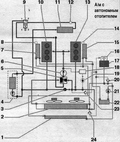
1. Front radiator for the charge air cooling circuit: after replacement, replace the coolant. 2. System radiator. cooling: cars with DSG gearbox: with built-in ATF radiator; after replacement, change the coolant. 3. Coolant temperature sensor "G62". 4. Autonomous heater: with circulation pump "V55". 5. Thermostat. 6. Water pump. 7. Right intercooler: in the compressor housing; after replacement, change the coolant. 8. Air bleed screw. 9. Climatronic coolant supply shut-off valve "N422": controlled by the Climatronic control unit "J255". 10. Cylinder head, bank 1 (right); after replacement, change the coolant. 11. Heater heat exchanger: after replacement, change the coolant. 12. Ventilation hole. 13. Cylinder head, row 2 (left): change the coolant after replacement. 14. Air bleed screw. 15. Left intercooler: in the compressor housing; after replacement, change the coolant. 16. Expansion cap. coolant reservoir: checking the pressure reducing valve. 17. Expansion tank. 18. Oil cooler. 19. Coolant pump for priming after switching off the engine "V51": variant for the national market. 20. Check valve: in the system hose. cooling. 21. Intercooler pump "V188". 22. Left cooler of the charge air cooling circuit: after replacement, change the coolant. 23/24. Check valve: in the system hose. cooling.
Draining and filling the coolant
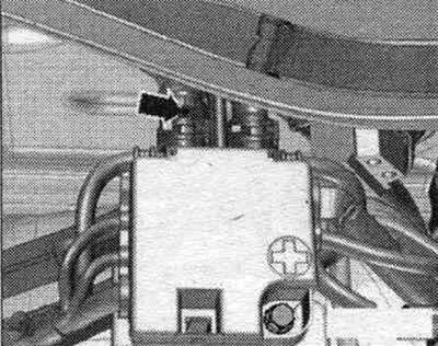
Open the expansion lid. tank.
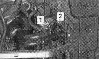
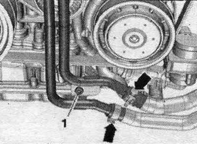
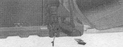
Remove the front sound insulation "1". Install a service tray under the engine. Unscrew the drain plug "1" and drain the coolant. Ignore "Pos. 2".
Remove the coolant hose from the engine oil cooler by loosening the hose clamp "arrow" and drain the coolant. For clarity, the parts in the following illustrations are shown with the engine removed.
Car with system pipes. cooling in the front left part, version 1
Loosen clamps "1" and "3", disconnect the hoses from the system pipes. cooling system in the front left part and drain the remaining coolant. Ignore "Pos. 2".
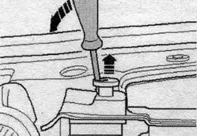
Car with system pipes. cooling in the front left part, version 2
Loosen the arrow clamps and disconnect the hoses from the system pipes. cooling system in the front left part and drain the remaining coolant. Ignore "Pos. 1".
Bay
The ignition is off.
Note: The cooling system is filled with a coolant solution and coolant additives for the entire year. Only the concentrate approved for the given engine should be used. Other concentrates may worsen the properties of the coolant, especially its anti-corrosion properties. The resulting damage may cause leaks in the system. cooling and lead to serious engine malfunctions. The coolant additive reduces damage from frost and corrosion, as well as calcium deposits. In addition, it increases the boiling point. Therefore, the concentrate must be present in the cooling system throughout the year. Especially in countries with tropical climates and high engine loads, coolants with a high boiling point reliably protect the engine during operation. The freezing point of the coolant must be at least -25°C, and at least -35°C in countries with an arctic climate. It is also prohibited to reduce the proportion of concentrate in the coolant during the warm season or when operating in countries with a warm climate by adding it to the system. cooling water. The concentrate content should be at least 40%. If climatic conditions require enhanced freeze protection, the concentrate content can be increased. However, only up to 60% (freezing temperature down to -40°C), since the level of protection will decrease again and the cooling effect will deteriorate. Use only clean drinking water to mix coolant. Reusing drained coolant is permitted only if the radiator, heater heat exchanger, cylinder head, cylinder head gasket or cylinder block have not been replaced. To secure all hose connections, use clamps of the appropriate series. Replace the seal. air bleed screw rings on charge air coolers. To check the concentrate in the cooling system, use the T10007 refractometer.
Close the drain plug "1". Connect the coolant hose to the engine oil radiator "arrow".
Car with system pipes. cooling in the front left part, version 1
Connect coolant hoses "1" and "3" to the front left coolant pipes.
Car with system pipes. cooling in the front left part, version 2
Connect the "arrow" hoses to the system pipes. cooling on the left in the front part.
All
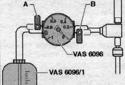
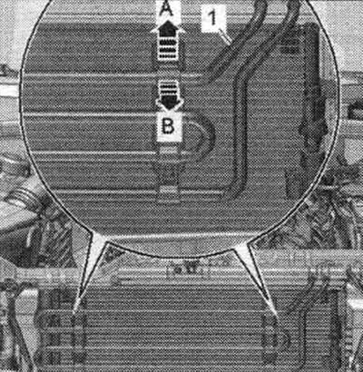
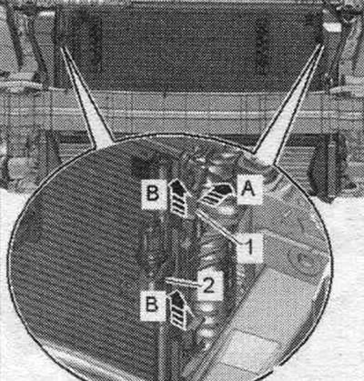
Pour into the tank of the device for filling the system. cooling "VAS 6096" 12 liters of pre-mixed coolant in the correct proportion: coolant (40%) and water (60%) for freezing temperatures down to -25°C. Coolant (50%) and water (50%) for freezing temperatures down to -35°C. Screw on the system tester adapter. cooling "VAG1274/8" to the expansion tank. Install the device for filling the system. cooling "VAS 6096" on the adapter "VAG 1274/8". Place outlet hose "1" into a small container "2". The exhaust air will capture a small amount of coolant, which must be collected. Close taps "A" and "B" by turning them perpendicular to the direction of flow. Connect hose "3" to the compressed air line. Pressure: 6...10 bar.
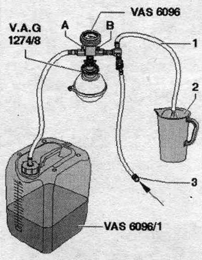
Open valve "B" by turning it in the direction of flow. In the cooling system, the ejector pump creates reduced pressure. The indicator arrow should move into the green field. Open valve "A" briefly by turning the handle in the direction of flow so that the hose expands. system tank. the "VAS 6096" cooling system was filled with coolant. Close valve "A" again. Open valve "B" for 2 minutes. The ejector pump continues to create negative pressure in the cooling system. The indicator arrow should remain in the green field. Close valve "B." The indicator arrow should remain in the green field, indicating that the reduced pressure in the cooling system is sufficient for subsequent filling. If the arrow is below the green field, then you should repeat the previous operations. When the vacuum decreases, check the system. cooling for leaks. Remove the compressed air hose. Open valve "A". Due to the vacuum in the cooling system, the coolant coming out of the tank of the system filling device will flow. cooling "VAS 6096" The coolant is sucked in and fills the system..
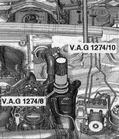
Remove the system filling device. cooling "VAS 6096" with adapter "VAG 1274/8" on expansion. tank. Attach the tube "VAG1274/10" on the adapter "VAG 1274/8". Fill with coolant until the system tester tube reaches the level. the cooling system was completely filled. If necessary, add more during the air removal process.
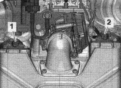
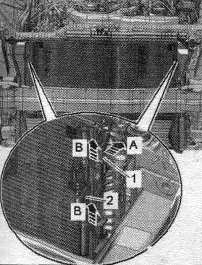
Remove the rear engine cover "2" upward. Open the air bleed screws "1" and "2" sequentially until the coolant drains. Close the bleed screws.
Remove the seal from the partition of the water drainage box. Remove the water drainage box cover.
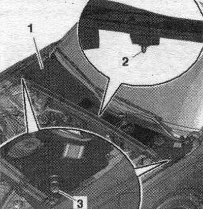
Loosen and remove the system hose. cooling, going to the heat exchanger, so that the coolant comes out of the vent hole "arrow" in the system hose. cooling.
Place the coolant hose onto the connecting nipple and secure it. On a vehicle with independent heating, turn on the heater for approx. for 30 seconds. Screw on the expansion cap. tank until it clicks. Start the engine. Set the temperature for all zones to "HI" and the lowest ventilation level (= 0). Turn off the air conditioner compressor. to do this, press the AC button. The tester LED in the button should not light. Run the engine at 2000 rpm for 3 minutes. Let the engine idle until the two large coolant hoses on the radiator warm up. The engine should run at 2000 rpm for 2 minutes. Turn it off and let the engine cool. Install soundproofing. Check the coolant level. When the engine is cold, the coolant temperature should be at the MAX mark. When the engine is warm, the coolant level should be above the MAX mark.
Cooling system pump, thermostat, fittings
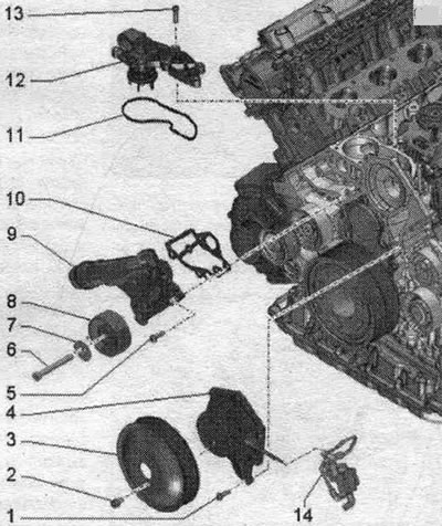
1. Bolt: 9 Nm. 2. Bolt: 20 Nm. 3. Belt drive pulley for water pump. 4. Water pump: with seal. 5. Bolt: 9 Nm. 6. Bolt. 7. Washer. 8. Poly V-belt idler roller. 9. Connecting pipe of the system hose. cooling. 10/11. Gasket: replace. 12. Thermostat. 13. Bolt: 9 Nm. 14. System circuit valve. cooling of the cylinder head "N489".
Removal and installation the water pump
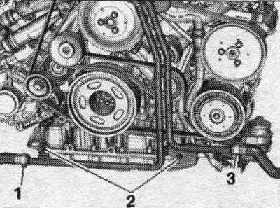
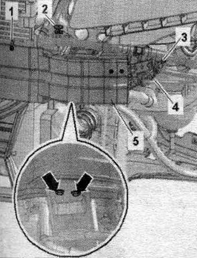
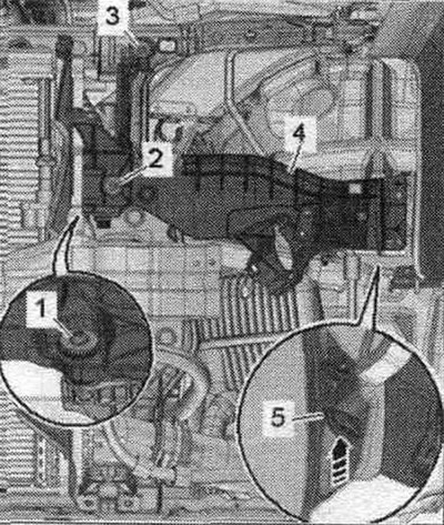
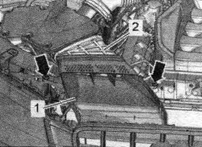
Drain the coolant. Remove the front left coolant pipe. Loosen bolts "1" and "2" and remove the coolant pipes. Disconnect the poly V-belt from the air conditioning compressor, but do not remove it completely.
Remove the system hose. cooling from the front coolant pipe, to do this, press the fastening bracket "arrow".
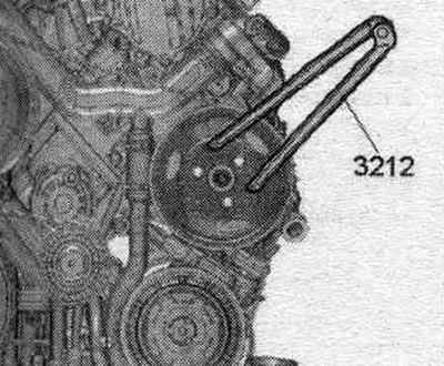
Unscrew the bolts of the poly V-belt pulley for the coolant pump, for this use a 2-hole wrench "3212" as a counter support.
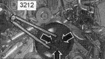
A/m with hydr. power steering: Loosen the bolts securing the poly V-belt pulley for the power steering pump drive, using a 2-hole nut wrench "3212" as a stop.
Cars with electric power steering: Remove the system valve. cooling cylinder head "N489" "arrow" from the holder and put aside.
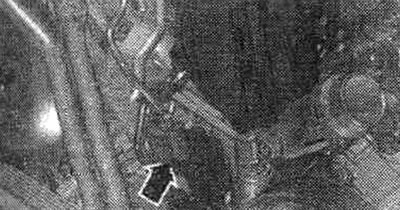
Disconnect vacuum hose "1".
All
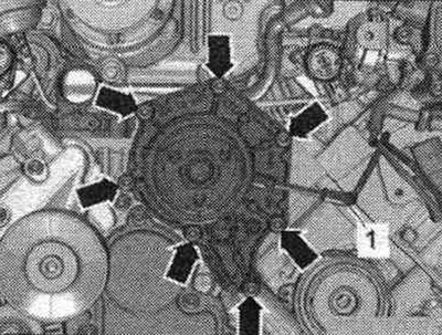
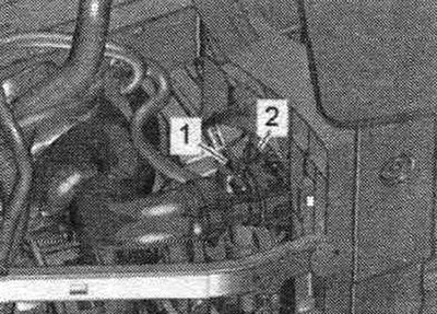
Unscrew the coolant pump arrow bolts, remove the pump and put it aside.
Install
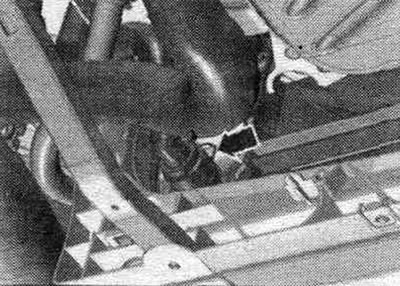
Installation in reverse order. Clean the sealing surfaces from oil and grease. Install the poly V-belt pulley of the impeller pump. Connect the coolant hose to the nipple connector. Install the poly V-belt. Install the coolant pipes. Fill with coolant.
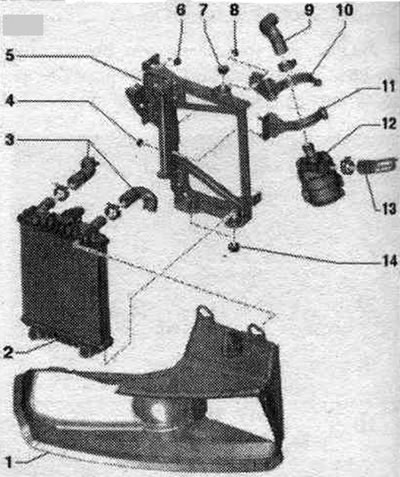
Coolant supply pipes
Execution 1
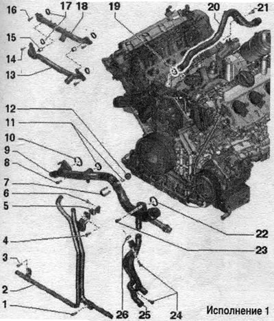
1. Bolt: 9 Nm. 2. Front left coolant pipe. 3/4. Bolt: 9 Nm. 5. Bracket. 6. Bolt: 22 Nm. 7. Clips. 8. Bolt: 9 Nm. 9. Front coolant supply pipe. 10. Lip seal: replace. 11. Sealing rings: replace. 12. Coolant temperature sensor "G62". 13. Lower coolant pipe to compressor: remove and install together with "pos. 17". 14. Bolt: 5 Nm. 15. Centering sleeve: 2 pcs. 16. Screw: 5 Nm. 17. Gaskets: replace. 18. Upper coolant pipe to compressor: remove and install together with "pos. 11". 19. Sealing ring: replace. 20. Upper coolant supply pipe. 21. Bolt: 9 Nm. 22. Gasket: replace. 23. Bolt: 9 Nm. 24. Bolts: 9 Nm. 25. Left coolant pipes. 26. Sealing ring: replace.
Execution 2
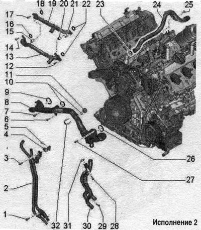
1. Screw: 9 Nm. 2. Front left system pipe. cooling. 3. Screw: 9 Nm. 4. Bracket. 5. Bolt: 22 Nm. 6/7. Screw: 9 Nm. 8. Front system pipe. cooling. 9/10. Sealing ring: replace. 11. Coolant temperature sensor "G62". 12. Screw: 5 Nm. 13. Lower coolant pipe to compressor: remove and install together with "pos. 19". 14. Screw: 5 Nm. 15. Centering sleeve. 16. Gasket: replace. 17. Screw: 5 Nm. 18. Gasket: replace. 19. Upper coolant pipe to compressor: remove and install together with "pos. 13". 20. Centering sleeve. 21. Screw: 5 Nm. 22. Gaskets: replace. 23. Sealing ring: replace. 24. Upper system pipe. cooling. 25. Screw: 9 Nm. 26. Gasket: replace. 27-29. Screw: 9 Nm. 30. Left system pipes. cooling. 31. Sealing ring: replace. 32. Clamp.
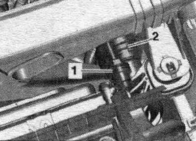
Intercooler pump "V188" - tightening torque
Tighten nut "2" to 9 Nm.
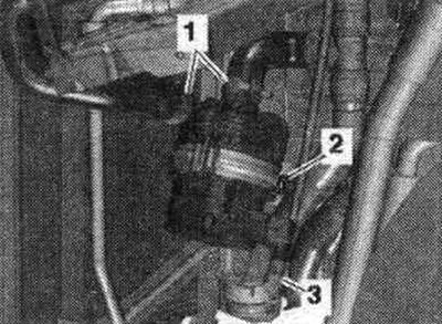
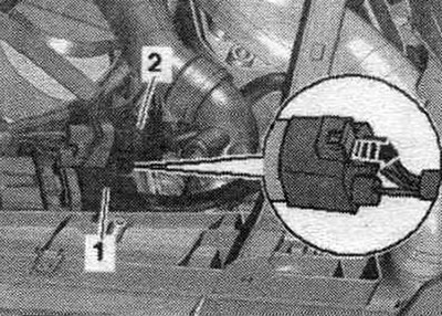
Coolant recovery pump "V51"
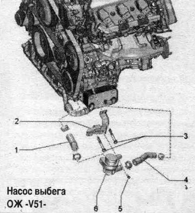
1. Cooling system hose. 2. Bracket. 3. Bolts: 9 Nm. 4. Cooling system hose. 5. Bolt: 4 Nm. 6. Coolant bleeding pump after engine shutdown "V51".
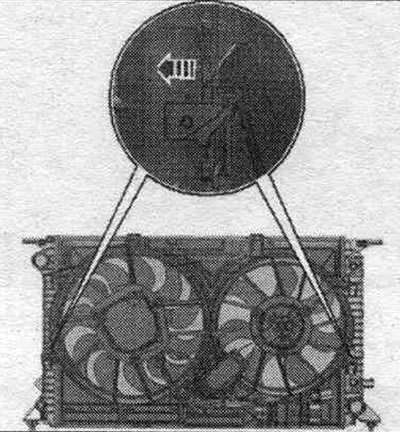
Radiator system. cooling, front radiator for charge air cooling circuit, frame and fans - version 1
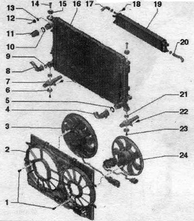
1. Bolt: 4.5 Nm. 2. Fan frame. 3. Radiator fan "V7": with fan control unit "J293". 4. Cooling system hose: to remove, release the clamp; connect to the radiator. 5. Sealing ring: replace. 6. Lining. 7. Radiator console. 8. Cooling system hose: to remove, loosen the clamp; connect to the radiator. 9/10. Sealing ring: replace. 11/12. Cooling system hose: loosen clamp to remove; connect to the radiator. 13. Sealing ring: replace. 14. Lock bolt: unlock with a screwdriver and remove. 15. Rubber support: for radiator. 16. Coolant radiator: removal and installation together with the fan frame; after replacement, change the coolant. 17. Cooling system hose. 18. Bolt: 4.5 Nm. 19. Front charge air cooler. 20. Cooling system hose. 21. Rubber support: for radiator. 22. Bolt: 5 Nm. 23. Bolt: 4.5 Nm. 24. Radiator fan 2 "V177".
Radiator frame and fans - version 2
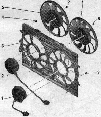
1. Radiator fans "V7": with fan control unit "J293". 2. Radiator fan 2 "V177": with fan control unit 2 "J671". 3. Fan frame. 4. Screw: 3.5 Nm. 5. Fan impeller: your finger should fit into the hole. 6. Screw: 5 Nm. 7. Fan impeller: the finger should enter the hole. 8. Screw: 5 Nm. 9. Screw: 3.5 Nm.
Left-side charge air cooler
1. Air duct. 2. Left cooler of the charge air cooling circuit. 3. Water hoses. 4. Nut: 9 Nm. 5. Bracket. 6. Nut: 9 Nm. 7. Rubber support: for radiator. 8. Nut: 9 Nm. 9. Cooling system hose. 10/11. Bracket. 12. Intercooler pump "V188". 13. Cooling system hose. 14. Rubber support: for radiator.
Connecting the coolant hose with nipple connectors
Remove the old seal. ring "2" from coolant hose "3". Moisten the new seal. coolant ring and insert it into the coolant hose. Push the coolant hose onto the coolant pipe "1" until it clicks into place. Press the coolant hose in again and pull the hose to ensure that the coupling is properly secured.
Removal and installation the coolant radiator with fan frame
The coolant radiator and fan frame can only be removed and installed as an assembly. In new designs, the condenser can no longer be removed from the radiator with the refrigerant hoses still connected. In the following description of the work, this design is referred to as "Version 2." Remove the front noise insulation cover "1." Remove the safety bar "5." Remove the front charge air cooler.
Vehicles with refrigerant hoses in version 2: Remove the condenser.
Remove the panel bracket to install the headlight housing.
Place a VAS 6208 oil pan under the engine. Unscrew drain plug 1 and drain the coolant. Then remove the coolant hose from the radiator by loosening the retaining clip 2.
Remove the connecting nipple from the radiator by loosening the "arrow" clamp.
Before starting work in the fan frame area, disconnect the plug connectors. Disconnect the plug connectors "1" and "2" of the radiator fan by moving the latch back "arrow" and pressing on the locking tabs.
Vehicles with dual clutch transmission 0B5: Install a device for pumping and collecting oil under the disconnect point. Loosen the arrow bolts and disconnect the ATF lines from the radiator. To prevent ATF oil leakage, tie the ATF lines to the side member. Close open lines and pipes with clean plugs from the VAS 6122 engine plug kit.
All
Remove the connecting nipple from the radiator by loosening clamps "1" and "2".
Loosen the "arrow" bolts. Remove the air duct "1" from the intermediate flange "2" of the air duct housing. filter.
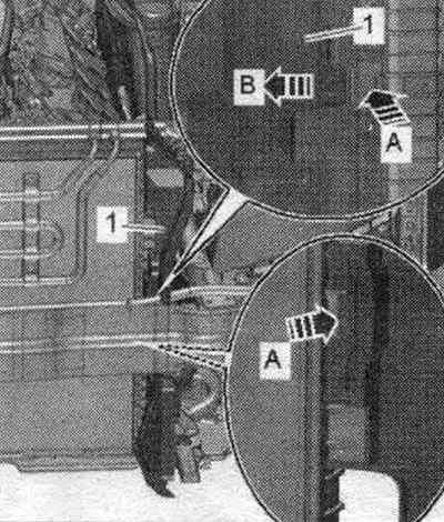
A/m with hydraulics. power steering: If equipped, unlock the fastening brackets "arrow A" and move the coolant hoses "1" of the power steering forward "arrow B". Remove the power steering hoses from the condenser in an upward direction and place them on the engine.
All
Release the clamps "arrow A" and remove the air duct "1" on the left and right "arrow B".
Release the radiator retainers on the left and right and remove them upwards "arrows".
Unscrew the bolts "1" on the left and right and remove the console and radiator from the radiator frame "arrow". Lower the radiator slightly.
Vehicles with refrigerant hoses in version 1: The second mechanic must unlock the fastening brackets "1" "in the direction of arrow A"; the first mechanic must lift the condenser "2" upwards out of the retainers on the radiator "arrows B". Tilt the condenser with the connected coolant hoses forward.
All
Remove the radiator. Press the locking tabs of the fan frame on the left and right "arrow" simultaneously and remove the fan frame from the radiator in an upward direction.
Install
Installation in reverse order. For small indentations on the plates. Install the air duct of the intermediate flange of the air housing. filter. Cars with 0B5 DSG gearbox: screw on the ATF lines. Connect the coolant hose to the nipple connector. Install the front charge air cooler. Install the panel bracket to the headlight housing. Install the capacitor. Install a safety bar. Fill with coolant. If the radiator was replaced, change the coolant.
Vehicle with DSG 0B5 gearbox: check the ATF level.
(The full version is posted on the resource audimanual)