
Table of contents: Ignition system ↓ Removal and installation knock… ↓
Ignition system
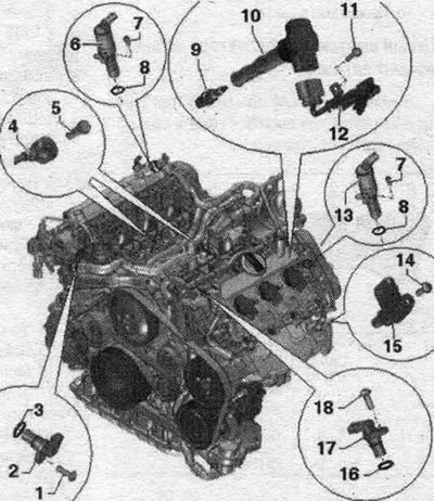
1. Bolt: 9 Nm. 2. Hall sensor "G40". 3. Sealing ring: replace. 4. Knock sensors: knock sensor 1 "G61" (cylinder bank 1), knock sensor 2 "G66" (cylinder bank 2). 5. Bolt: 20 Nm; tightening torque affects the operation of knock sensors. 6. Valve 1 for adjusting the timing phases "N205". 7. Bolt: 5 Nm. 8. Sealing ring: replace. 9. Spark plug. 10. Coil. 11. Bolt: 5 Nm. 12. Wiring harness. 13. Valve 2 for adjusting the timing phases "N208". 14. Bolt: 9 Nm. 15. Engine speed sensor "G28". 16. Sealing ring: replace. 17. Hall sensor 2 "G163". 18. Bolt: 9 Nm.
Removal and installation coils
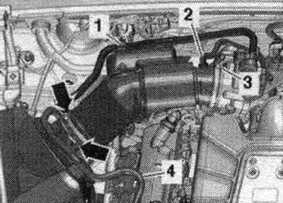
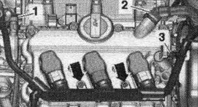
Remove engine covers "1" and "2" upwards. Disconnect the fuel. line "4" and line "1" from the absorber with activated carbon on the air duct body. filter and on the air duct tube. Disconnect vacuum hose "2" from the air duct hose connection. Remove the air duct hose by loosening the hose clamp "3" and opening the clamps "arrow". Remove the air duct housing. filter.
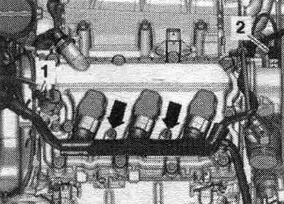
Unscrew the arrow bolts and disconnect the plug connectors from the coils. Gently press the wire harness downwards. "Pos. 1, 2" do not take into account.
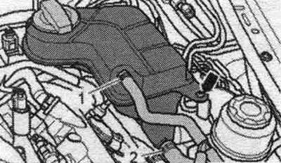
Cylinder bank 2 (left): Loosen the bolt "arrow". Disconnect the connector of the low coolant level indicator sensor "F66" from below on the expansion joint. tank and put the expansion tank with coolant hoses "1" and "2" connected to the side.
Unscrew the arrow bolts and disconnect the plug connectors from the coils. Gently press the wire harness downwards. "Pos. 1, 2, 3" do not take into account.
All
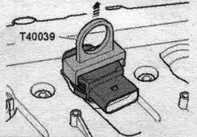
Remove the coils using the "T40039" puller.
Installation in reverse order.
Removal and installation knock sensors "G61"/"G66"
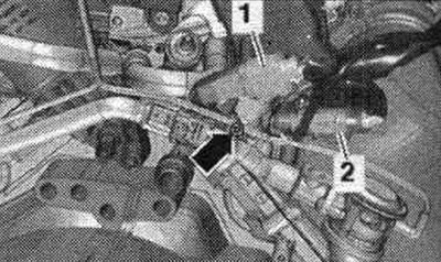
Remove the compressor. Remove the lower parts of the left and right intake manifolds. Remove the plug connector "1" of the knock sensor 1 "G61" from the right bracket and disconnect it. "Pos. 2" and "arrow" should not be taken into account.
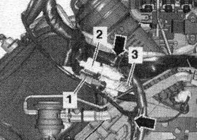
Remove the plug connector "2" of the knock sensor 2 "G66" from the left bracket and disconnect it. "Pos. 1, 3" and "arrows" are not taken into account.
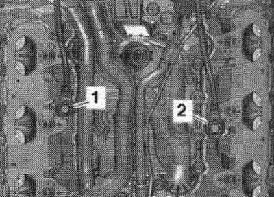
Unscrew bolt "1" of knock sensor 1 "G61" and bolt "2" of knock sensor 2 "G66", remove the knock sensor.
Install
Installation in reverse order. Install the lower sections of the left and right intake manifolds. Install the compressor.
Verification data
| Idle speed | It is not manually adjustable; adjustment is made by stabilizing the idle speed |
| Ignition timing | Not adjustable, installed in the control unit. |
| Ignition system | Ignition system with 6 separately located ignition coils (with integrated output stages), which are placed directly on the spark plugs through the spark plug tip. |
| Cylinder firing order | 1-4-3-6-2-5 |
The original text of the material can be found on the website: audimanual