
Table of contents: Lower part of the oil. pan, upper… ↓ Removal and installation the lower… ↓ Removal and installation of oil. pump ↓ Oil filter housing, oil pressure… ↓ Removal and installation the oil… ↓ Removal and installation of the oil… ↓ Remove and install the oil pressure… ↓ Check oil valves, oil separators ↓ Removal and installation the cover… ↓
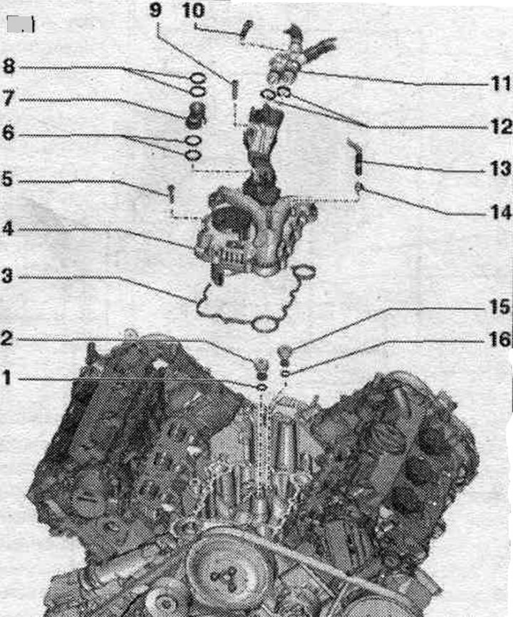
Lower part of the oil. pan, upper part of oil. sump, oil pump, engine oil cooler
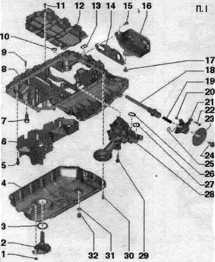
1. Nut: 9 Nm. 2. Oil level and temperature sensor "G266". 3. Lip seal: replace. 4. Lower part of oil. pallet. 5. Bolt: replace; 3 Nm + turn 90° further. 6. Lower oil separator. 7. Bolt: replace. 8. Upper part of oil. 9. Guide bushing: 2 pcs. 10. Sealing ring: insert into camshaft frame, replace. 11. Bolt: insert with threaded varnish; 9 Nm. 12. Upper oil separator. 13. Gasket: Insert into the camshaft frame; 14. Gasket: replace. 15. Bolt: 9 Nm. 16. Oil cooler: follow instructions; with oil radiator bypass valve. 17. Bolt: 9 Nm. 18. Drive shaft oil. pump. 19. Pressure spring. 20. Bushing: 2 pcs. 21. Support bracket. 22. Bolt: 9 Nm. 23. Oil sprocket. pump: can be installed on the drive shaft in only one position. 24. Bolt: replace; to loosen and tighten, hold the sprocket with a 2-hole wrench "3212"; 30 Nm + 90° further. 25. O-ring: replace. 26. Gasket: replace. 27. O-ring: replace. 28. Oil pump: do not disassemble. 29. Bolt: 20 Nm. 30. Bolt: replace. 31. Lip seal: replace. 32. Oil drain plug: 30 Nm.
Lower part of the oil. pallet - last and tightening torque of bolts
Bolts tightened at the tightening angle should be replaced. Tighten the bolts in 2 stages as follows.
| Step | Tightening torque/rotation angle |
| 1 | Crosswise 3 Nm |
| 2 | Turn crosswise by 90° |
Upper part of the oil. pallet - last, and tightening torque of bolts
Bolts tightened at the tightening angle should be replaced. Tighten the bolts in 2 stages as follows.
| Step | Bolts | Tightening torque/rotation angle |
| 1 | "1...6" | Crosswise 8 Nm |
| 2 | "1...6" | Turn crosswise by 90° |
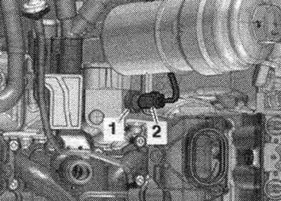
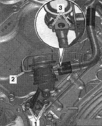
Oil level and temperature sensor "G266"
Drain the oil. Disconnect plug connector "3". Unscrew nuts "1" and remove oil level and temperature sensor "0266" "pos. 4".
Install
Installation in reverse order. Replace the seal. ring "2". Fill with oil and check its level.
Removal and installation the lower part of the oil. pallet
Drain the oil.
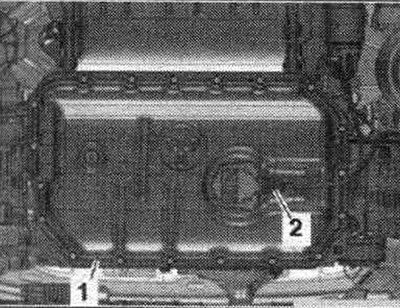
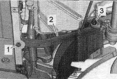
Cars without coolant recovery pump "V51": Unscrew screw "1" and nut "3" and remove the left pillar "2" of the front support panel.
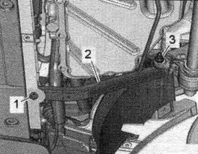
Unscrew the bolts "arrows" and secure the engine oil radiator with the coolant hoses "1" and "2" connected to the side.
Cars with a "V51" coolant recovery pump: Remove the "V51" coolant recovery pump. Loosen the "arrow" nuts and lower the stabilizer.
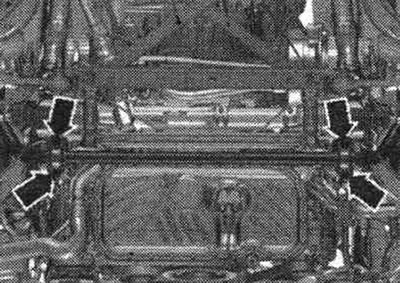
Vehicles with dual-clutch transmission 0B5: Remove the ATF line bolts "arrow". Ignore "Pos. 1, 2".
All
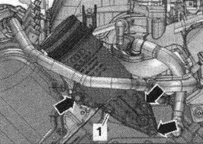
Disconnect plug "2" of the oil level and temperature sensor "G266" and release the electrical wiring. Unscrew the bolts of the lower part of the oil. pan "1". Carefully disconnect the lower part of the oil. the pallet from the gluing point, without bending it.
Installation
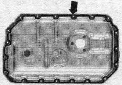
Replace the gaskets. If the coating on the bottom of the oil. the pan is damaged or the lower part of the oil. the pallet is bent, replace it. Remove any remaining sealant from the bottom and top of the oil. tray, for example, using a rotating brush with plastic bristles. In this case, do not allow damage to the coating of the lower part of the oil. pallet. Clean the sealing surfaces from oil and grease. Observe the expiration date of the sealant. Cut off the tube tip along the front mark (opening diameter approx. 1 mm). Risk of blockage of system channels. lubrication in case of excess sealant. The sealant bead should not be thicker than the specified size. Apply the "arrow" silicone sealant to the clean seating surface of the lower part of the oil. pallet as shown in the figure. The thickness of the sealant bead is about 1.5 mm. Install the lower part of the oil seal. pallet within 5 minutes after applying the sealant.
Install the lower part of the oil. pallet and tighten the bolts. Installation in reverse order.
Vehicles with dual clutch transmission 0B5: Install ATF lines.
All
Install the stabilizer. Install the engine oil cooler. Fill with oil and check its level.
Removal and installation of oil. pump
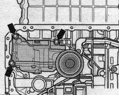
Removing the lower part of the oil. crankcase. Loosen the "arrow" bolts. Remove the oil pump forward from the drive shaft.
Install
Installation in reverse order. Replace the seal and gasket. ring. Install oil. pump onto the drive shaft and tighten. Install the lower part of the oil. pan. Fill with oil and check its level.
Oil filter housing, oil pressure sensor
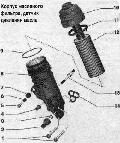
1. Bolt: 13 Nm. 2. Oil pressure sensor "F22": switching pressure 2.5...3.2 bar, with gray electrical tape; check in Guided Fault Finding; 20 Nm. 3. Lip seal: replace. 4. Flange nut: 13 Nm. 5. Bolt: 9 Nm. 6. Bushing. 7. Rubber tip. 8. Oil filter housing: with filter bypass valve, with oil check valve; the oil check valve does not change. 9. Sealing ring: replace. 10. Cover: 25 Nm. 11. Lip seal: replace. 12. Oil filter element. 13. Threaded pin. 14. Gasket: replace.
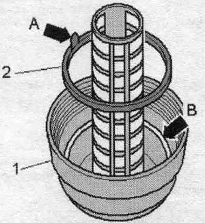
Replace the seal. threaded plug ring
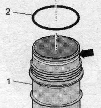
Remove the seal. ring "2" of the projection for removing "arrow A" from the locking cover "1". Insert a new seal. ring with a semicircular profile in the "arrow B" groove on the locking cover. The "arrow A" tongue must be facing upwards.
Installing the sealing ring on the oil filter housing
Insert the seal. ring "2" into the groove "arrow" of the oil filter housing "1".
Low pressure oil pressure sensor "F378"
1. Low pressure oil pressure sensor "F378": switching pressure 0.75...1.05 bar, with grey insulating tape; check in Guided Fault Finding; 20 Nm
Removal and installation the oil filter housing
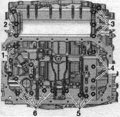
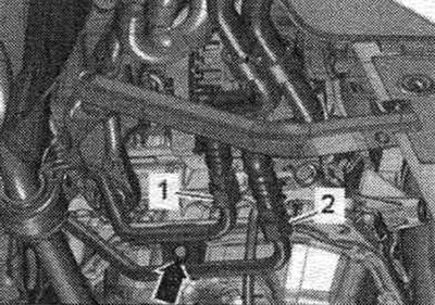
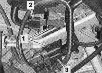
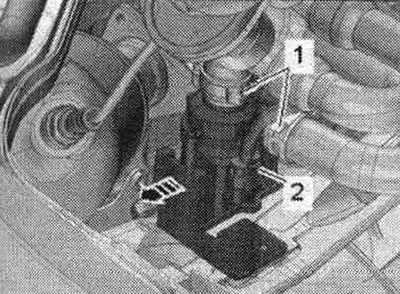
Remove the rear engine cover "2" upwards. Remove the oil filter element. Use an oil suction tool to pump out the oil from the oil filter housing. Remove the front wall of the water drainage box. Release the electrical wires. Unscrew bolts "1" and put the bracket with connectors aside. "Pos. 2, 3" do not take into account.
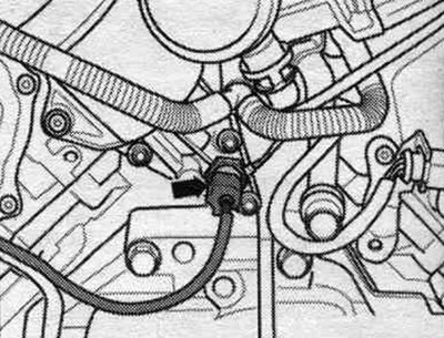
Disconnect the "arrow" connector of the oil pressure sensor "F22".
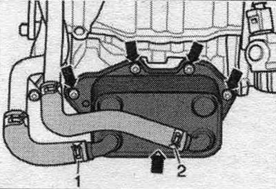
Unscrew bolts "3" and push back the secondary air supply hose. "Pos. 1, 2" do not take into account.
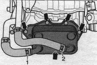
Loosen the "arrow" bolts. Unscrew nut "1" and the double bolt, and remove the oil filter housing.
Install
Installation in reverse order. Replace the gasket, cuffs and seals. ring. Install the secondary air supply hose. Install the front wall of the water drainage box. Install the oil filter element. Fill with oil and check its level.
Removal and installation of the oil pressure sensor "F22"
Remove the rear engine cover "2" upward. Push aside the electrical wiring on the left side of the water drain box bulkhead.
Car with a circulation pump system. cooling "V50", version 2
Unlock the "arrow" lock, remove the system circulation pump. cooling "V50" from the bracket and put it aside. "Pos. 1, 2" do not take into account.
All
Disconnect the "arrow" connector by sliding the stopper back and pressing down on the retainer. Unscrew the oil pressure sensor "F22".
Install
Installation in reverse order. Replace the seal. ring. To avoid oil loss, immediately insert a new "F22" oil pressure sensor into the hole. Check the oil level.
Remove and install the oil pressure regulating valve "N428"
Cars without a coolant recovery pump "V51": Remove the front noise insulation "1". Unscrew the bolt "1" and nut "3", remove the left brace "2" of the radiator frame.
Install a device for pumping and collecting oil under the engine. Unscrew the bolts "arrows" and secure the engine oil radiator with the coolant hoses "1" and "2" connected to the side.
Cars with coolant recovery pump "V51": Remove "V51".
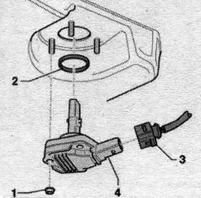
All
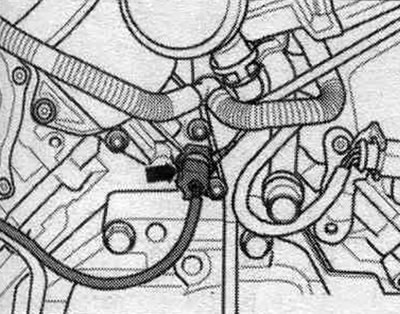
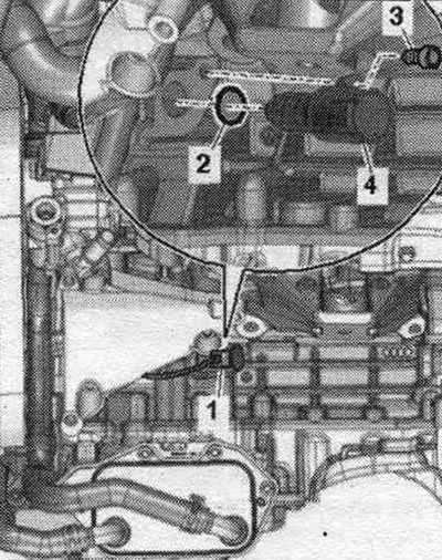
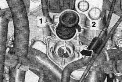
Disconnect plug connector "1". Unscrew bolt "3" and pull out oil pressure regulating valve "N428" "pos. 4".
Install
Installation in reverse order. Replace the seal. ring "2". Tighten the oil pressure regulating valve bolt "N428". Install the engine oil cooler.
Checking oil pressure
The oil level is normal. Oil temperature is approximately 80°C. Remove the "F22" oil pressure sensor. Connect the "VAG 1342" pressure gauge to the oil pressure sensor port. Screw the oil pressure sensor "F22" into the oil pressure gauge. Start the engine. Oil pressure at idle: not less than 1.2 bar. Oil pressure at 2000 rpm: not less than 1.5 bar.
Check oil valves, oil separators
1. O-ring: replace. 2. Oil pressure relief valve: for supplying oil to the right cylinder head; 20 Nm. 3. Gasket: replace. 4. Cover with oil separator: with system nipple. crankcase ventilation. 5. Bolt: 9 Nm. 6. - 7. Engine crankcase ventilation connecting pipe. 8. - 9. Bolt: 9 Nm. 10. Bolt: 3 Nm. 11. System hoses. crankcase ventilation hose to cylinder head covers. 12. O-rings: replace. 13. Crankcase ventilation hose: to air tube. 14. Hose clamp. 15. Oil pressure relief valve: for supplying oil to the left cylinder head; 20 Nm. 16. Sealing ring: replace.
Installing the crankcase ventilation connection pipe
Insert the crankcase ventilation pipe "1" with new sealing rings into the oil separator cover: Installation position: protrusion "2" must enter the guide "arrow".
Removal and installation the cover with oil separator
Remove the system hoses. crankcase ventilation. Removing the upper coolant pipe. Removing the lower part of the air intake on the left.

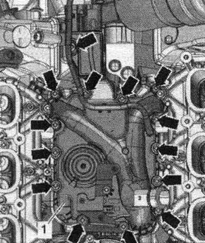
Loosen the "arrow" bolts. Remove the high-pressure line bracket and oil separator cover "1.".
Install
Installation in reverse order. Replace the gasket. Install the lower part of the intake manifold. Installing the upper coolant pipe. Install the system hoses. crankcase ventilation.
[The original publication in its entirety is posted on the website: AUDIMANUAL]