
Table of contents: Main dosing system (see diagram) ↓ Idle system (see diagram) ↓ Accelerator pump (see diagram) ↓
Main dosing system (see diagram)
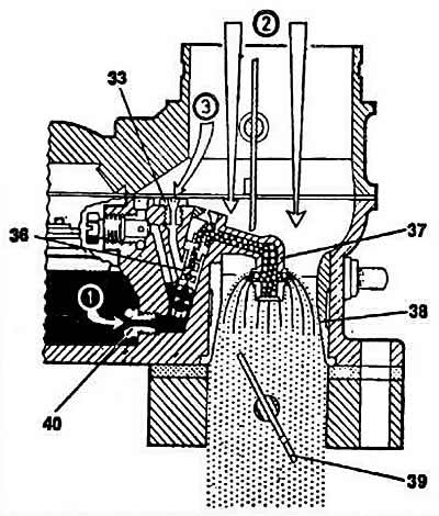
Main dosing system diagram: (1) - fuel intake; (2) - main air supply; (3) - air supply for pressure compensation; 33 - main air jet; 36 - emulsion tube; 37 - spray nozzle; 38 — diffuser; 39 - throttle valve; 40 - main fuel jet.
The outlet of the spray jet is located in the narrowest part of the diffuser. The spray jet is connected at the top to the hole into which the emulsion tube is pressed. A transverse channel connects the emulsion tube to the main air jet.
Through the main fuel jet located in the float chamber (access to which from the outside is possible after unscrewing the threaded plug), fuel enters the emulsion tube well. When the engine is not running, the fuel in the float chamber and the emulsion tube well is at the same level.
Under the action of the vacuum in the intake manifold, fuel is sucked through the main fuel jet and fed to the spray jet. At the top of the spray jet there is a small hole that prevents the occurrence of a siphon effect.
When the vacuum increases, some air enters through the main air jet and the pressure equalizes. The incoming air passes through the holes of the emulsion tube, mixes with the fuel passing through the main fuel jet, forming a fuel-air mixture (emulsion), and the composition of the mixture is regulated depending on the engine operating mode.
Idle system (see diagram)
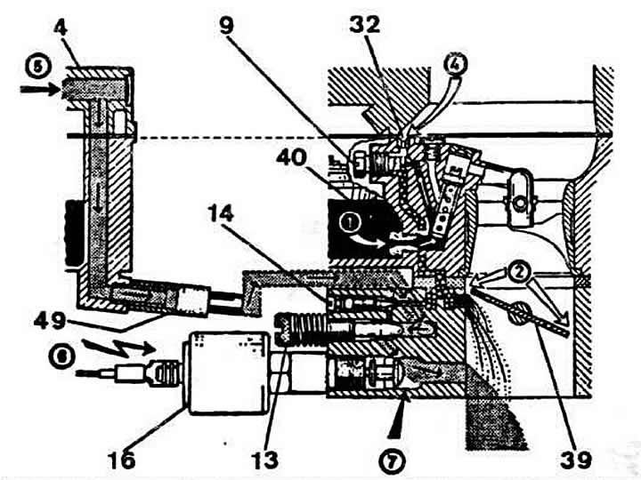
Scheme of carburetor operation in idle mode: (1) - fuel intake; (2) - main air supply; (3) - idle air intake; (5) — supply of fuel-air emulsion of the additional idle system; (6) — electromagnetic shut-off valve shoe (7) — electromagnetic shut-off valve in open position; 4 - carburetor cover; 9 — idle fuel jet; 13 — additional idle system mixture quantity adjusting screw; 14 — adjusting screw for idle mixture quality (composition); 16 - electromagnetic shut-off valve; 32 — idle air jet; 39 - throttle valve; 40 - main fuel jet; 49 — nipple.
The primary idle system is designed to prepare only a portion of the fuel-air mixture required for engine operation at a specific idle speed. The adjusting screws of this system are locked during assembly to prevent violation of the factory adjustment. The other portion of the fuel-air mixture required to ensure engine operation at idle speed is created in an additional circuit.
Fuel for the primary idle system is taken from behind the main fuel jet (normal idle mode) from the well of the emulsion tube, is dosed by the idle fuel jet, after which it mixes with the air supplied through the idle air jet, and forms an emulsion. This part of the emulsion is discharged downwards and combines with the fuel-air mixture created in the additional circuit in the channel in front of the electromagnetic jet.
The additional idle circuit also directs the fuel-air mixture to the gaps of the transition system. This ensures smoother operation of the carburetor during the transition from idle mode to the activation of the main metering system.
Fuel for the formation of a combustible mixture in the additional idle circuit comes from the float chamber through a calibrated tube and is dosed by a special nozzle.
The required air is sucked into the mixing chamber, where the fuel-air mixture is formed. An additional portion of the emulsion enters through an opening, the diameter of which is regulated by the mixture quantity adjustment screw of the additional idle system. The working mixture, the quantity of which depends on the position of the adjustment screw, is added to the emulsion flowing through the idle channel, and the entire volume of the mixture enters the mixing chamber. Air entering through the throttle valve gap, the size of which is precisely adjusted, is added to the combustible mixture obtained in this way. The process of preparing the working idle mixture is thus completed.
When the ignition is switched off, the electromagnetic shut-off valve closes the working mixture supply channel for the primary and additional idle systems. This eliminates the possibility of the engine running after the ignition is switched off.
When the adjusting screw of the additional idle system mixture quantity is loosened, the supply of the fuel-air mixture increases and, as a result, the engine crankshaft speed increases. Accordingly, when the adjusting screw is tightened, the supply of the fuel-air mixture of the additional idle system decreases and the crankshaft speed at idle speed decreases.
When adjusting the engine idle speed using the additional system mixture quantity adjusting screw, the fuel-air ratio in the working mixture formed in this circuit remains unchanged. Violation of the adjustment does not affect the CO content in the exhaust gases when the engine is idling. This significantly simplifies the adjustment of the engine idle speed.
Accelerator pump (see diagram)
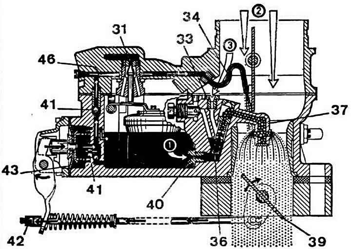
Accelerator pump operation diagram: (1) - fuel intake; (2) - main air supply; (3) - air supply for pressure compensation; 31 - float needle valve; 33 - main air jet; 34 - spray tube; 36 - emulsion tube; 37 - nozzle tip; 39 - throttle valve; 40 - main fuel jet; 41 - check ball valves (top - open, bottom - closed); 42 - adjusting nut; 43 — accelerator pump diaphragm.
When the throttle valve is opened sharply, the carburetor accelerator pump provides the injection of such an amount of fuel that will be sufficient to ensure smooth activation of the main fuel jet.
The cavity of the accelerator pump is filled with gasoline, which is pumped into the float chamber. In the idle position, the diaphragm of the accelerator pump is pressed against the drive lever by the spring. When the throttle valve is opened, the diaphragm moves forward, pumping fuel through the spray tube into the mixing chamber. The performance of the accelerator pump depends on the amount by which the drive lever is deflected at the moment of acceleration.
A check ball valve prevents fuel from returning to the float chamber during injection. Another ball valve at the outlet of the accelerator pump channel blocks air from the mixing chamber to the pump cavity while fuel is being pumped into it.
At a certain vacuum level in the mixing chamber, an additional amount of fuel enters here through the accelerator pump channel, enriching the combustible mixture.
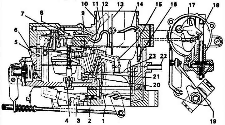
Solex 35 POSIT carburetor in section: 1 - throttle valve; 2 — adjusting screw for idle mixture quality (composition); 3 — additional idle system mixture quantity adjusting screw; 4 — power mode economizer valve; 5 - ball valves; 6 — idle jet; 7 - needle valve; 8 — economizer piston; 9 — idle air jet; 10 — float chamber ventilation channel; 11 - main air jet; 12 - accelerator pump nozzle; 13 — air damper; 14 — economizer injection tube; 15 — nozzle tip; 16 — economizer valve; 17 — air damper control cam; 18 — rod; 19 — throttle actuator limit screw; 20 - main fuel jet; 21 - emulsion tube; 22 — vacuum supply channel; 23 — diffuser.
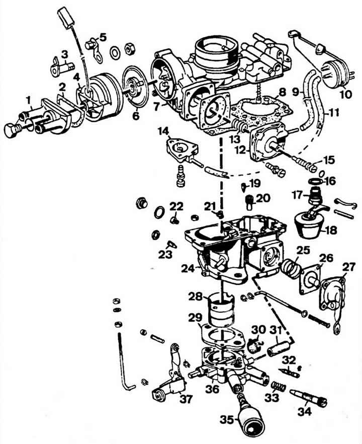
Main parts of the Solex 35 POSIT carburetor: 1-6 - parts of the automatic starting device; 7 — carburetor cover; 8 - gasket; 12, 14 — pneumatic drives of the air damper; 16, 17 - needle valve and gasket; 18 - float; 19, 20 — seat and needle valve of the power mode economizer; 21 - main air jet; 22 - main fuel jet; 23 - Stop screw; 24 — carburetor body; 25 - spring; 26 — accelerator pump diaphragm; 27 — lid; 28 — diffuser; 29 — spacer; 32 — adjusting screw for idle mixture quality (composition); 34 — additional idle system mixture quantity adjusting screw; 36 — throttle body.