
Table of contents: Valve seats ↓ Valve seat characteristics ↓ Valve guide bushings ↓ Valves ↓ Valve characteristics ↓ Clearances in the valve drive… ↓ Valve springs ↓ Valve drive levers ↓
The cylinder head is cast from aluminum alloy. The valve seats and guides are pressed into the cylinder head. The cylinder head gasket is installed with the "oben" mark and the number facing up (towards the cylinder head).
Warpage of the mating plane of the head with the cylinder block, no more than, mm: 0.1.
Permissible height of the cylinder head after grinding, not less than, mm: 167.30.
Valve seats
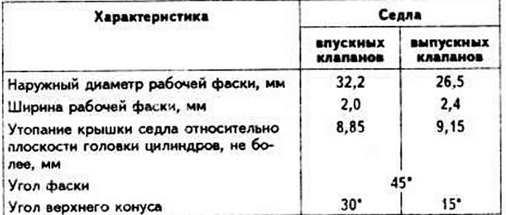
Valve seats are made of steel obtained by powder metallurgy methods and are not replaceable. If traces of burning or wear are detected that cannot be removed by grinding while maintaining the chamfer and upper cone angles and the width of the working chamfer of the seat, replace the cylinder head.
Valve seat characteristics
Valve guide bushings
The valve guide bushings are made of special brass and pressed into the cylinder head, which has been preheated in an oil bath or electric furnace to a temperature of 80-100°C.
Maximum permissible marginal clearance (when worn out) between the rod to the pallet and the guide bushing (for the measurement method, see subsection "Disassembly and assembly of the cylinder head"):
- for intake valves: 1.0;
- for exhaust valves: 1.3.
Valve guide bore diameter, mm: 8.013-8.035.
Valves
The valves are located in the cylinder head in rad and are actuated by the camshaft cams through levers. The exhaust valves are not subject to grinding.
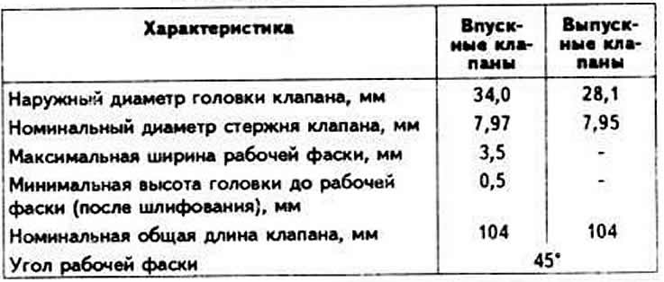
Valve characteristics
Clearances in the valve drive mechanism
The normal clearance between the back of the camshaft cam and the lever, measured with a feeler gauge, on a hot engine (coolant temperature over 35°C) is 0.20 mm for intake valves and 0.30 mm for exhaust valves; on a cold engine (after renovation) — 0.15 mm for intake valves and 0.25 mm for exhaust valves.
Valve springs
Each intake and exhaust valve has one spring. The intake and exhaust valve springs are identical.
Valve drive levers
Steel levers. The lever rests with its spherical recess at one end on the spherical head of the adjusting bolt with micrometric thread, designed to adjust the clearances in the valve drive mechanism. The return of the lever to the end of the valve stem and its retention on the spherical head of the adjusting bolt are provided by a plate steel spring. The adjusting bolt is screwed into a steel bushing installed in the cylinder head.